

- Battery Manufacturing Equipment
- Battery Laboratory Assembly Equipment
- Battery Pack Assembly Equipment
- Supercapacitor Assembly Equipment
- Dry Electrode Assembly Equipment
- Battery Laboratory Equipment
- Li ion Battery Tester
- Battery Safety Tester
- Battery Material Tester
- Film Coating Machine
- Rolling Press Machine
- Electrode Mixer
- Coin Cell Crimping Machine
- Coin Cell Electrode Disc Punching
- Pouch Cell Sealing Machine
- Pouch Cell Stacking Machine
- Pouch Cell Forming Machine
- Pouch Cell Ultrasonic Welder
- Pouch Cell Electrode Die Cutter
- Cylinder Cell Sealing Machine
- Cylinder Cell Grooving Machine
- Cylinder Cell Slitting Machine
- Cylinder Cell Winding Machine
- Cylinder Cell Spot Welding Machine
- Electrolyte Filling
- Type Test Cell
- Other Battery Making Machine
- NMP Solvent Treatment System
- Li ion Battery Materials
- Ni / Al / Cu Metal Foam
- Cathode Active Materials
- Anode Active Materials
- Coin Cell Parts
- Lithium Chip
- Cylindrical Cell Parts
- Battery Current Collectors
- Battery Conductive Materials
- Electrolyte
- Battery Binder
- Separator and Tape
- Aluminum Laminate Film
- Nickel Strip/Foil
- Battery Tabs
- Graphene Materials
- Cu / Al / Ni / Stainless steel Foil
- Vacuum Glove Box
- Lab Furnaces
- Ball Mill
- Hydraulic Press
- Laboratory Equipment
- Customized Electrode
Automatic Pouch Cell Laser Die Cutter Machine For Pouch Battery Electrode Cutting
Model Number:
TMAX-J550D-BGCompliance:
CE certificateWarranty:
One Year limited warranty with lifetime supportPayment:
T/T, Credit Card, Paypal, LC, Western UnionDelivery Time:
3 days
Automatic Pouch Cell Laser Die Cutter Machine For Pouch Battery Electrode Cutting
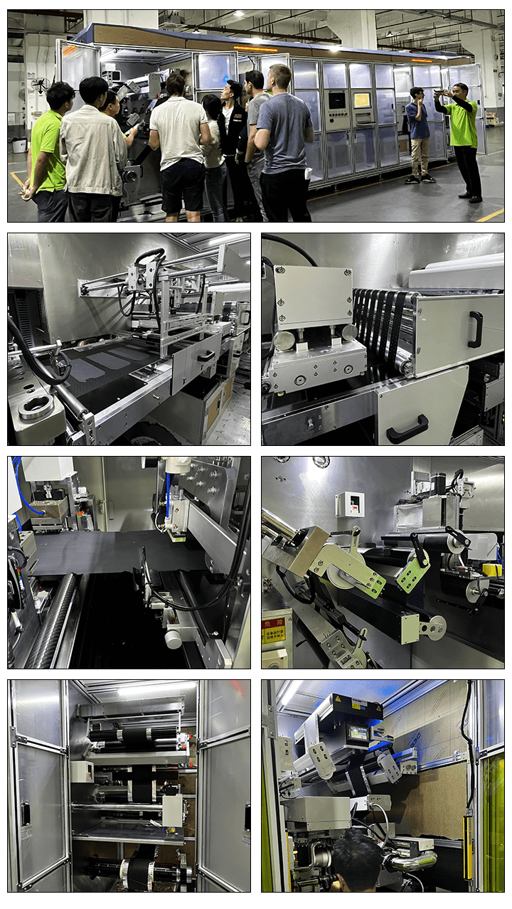
Ⅰ、Equipment Introduction
1.1 Overview of device functions :
This equipment is mainly used for the forming of positive and negative electrode plates in the stacking process of power batteries (continuous coating process).
AGV/manual installation of electrode coils on the unwinding inflatable shaft of the equipment, automatic unwinding of the equipment, automatic correction of the unwinding process by the correction mechanism, and control of the unwinding tension through the tension control system. Before entering the laser cutting, secondary correction (process correction) is carried out, electrode blade dust removal, tension control, electrode buffer, CCD defect detection, and the punching station uses hardware molds to punch V-angles, Then, the material is pulled to the cutting position through the pulling mechanism and cut into pieces. It is transported to the size inspection through a conveyor belt. After powder brushing inspection (on both sides), defective products are automatically removed into the NG material box, and qualified products are collected into the finished product box.
1.2 Action process:
放卷机构:Unwinding mechanism--放卷纠偏:Unwinding correction:--接带平台:Takeover platform--放卷张力:Unwinding tension--过程纠偏:Process correction--激光切割:Laser cutting--牵引机构:Traction mechanism--极耳除尘:Tab dust removal--张力机构 :Tension mechanism --储片机构:Film storage mechanism--瑕疵检测:Defect detection--V角裁切:V-angle cutting--拉切机构:Cutting mechanism--尺寸检测:Dimensional inspection--上刷粉:Upper brush powder--下刷粉:Lower brush powder--NG收料:NG receiving--OK 收料:OK receiving
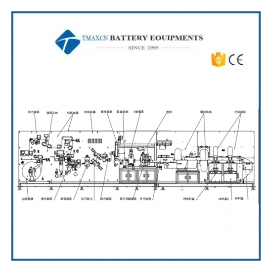
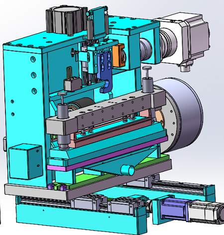
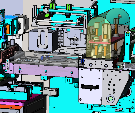
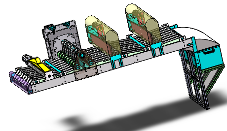
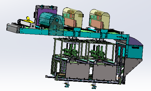
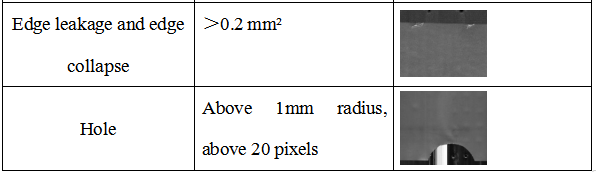
1.3 Equipment diagram: (single unwinding)
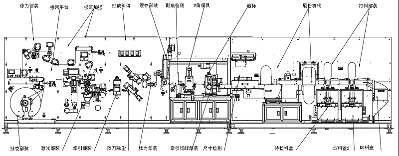
Equipment size:9000X2100X2600mm
张力部分:Tension section
接待平台:Reception platform
极耳加强:Tab reinforcement
形成纠偏:Rectify a deviation
缓存部件:Caching components
瑕疵检测:Defect detection
V角模具:V-angle mold
追标:Tracing
刷粉机构:Brushing mechanism
打料部件:Material parts
放卷部件:Unwinding components
激光部件:Laser components
风刀除尘:Wind knife dust removal
张力部件:Tension components
牵引切断部件:Traction cut-off components
尺寸检测:Dimensional inspection
待检料盒:Material box to be inspected
OK料盒:OK Material Box
NG料盒:NG Material Box
1.4 Equipment characteristics:
1) Single roll feeding mechanism: Each shaft can be fed with a maximum diameter of 700mm. The pneumatic expansion shaft adopts a special design to reduce the friction between the coil and the pneumatic expansion shaft, saving labor and time, and making material replacement convenient and fast; The automatic unwinding is driven by a servo motor, and the program controls the automatic unwinding. The size change of the pole piece coil is calculated through the coil diameter algorithm to determine whether the pole piece is about to be used up. When the coil is used up, the machine sends an alarm signal and automatically stops.
2) Pulling mechanism: The patented servo pulling mechanism is used, with a pulling accuracy of ± 0.2mm.
3) Material storage mechanism: Adopting servo+module drive and tension coordinated buffer, it can ensure continuous uncoiling during die-cutting, improve production efficiency, and ensure material drawing accuracy.
4) Pole cutting knife: adopts a patented cutting mechanism, with small powder loss and burrs. In addition, the device can adjust the positioning of the cutting tool based on the size of the electrode through servo drive, improving the width accuracy of the electrode.
5) Integrated function: This machine can integrate CCD detection and electrode powder brushing functions to improve the utilization rate of the entire machine.
6) Patent dust removal method: reduces secondary pollution of dust and effectively avoids damage to the electrode by brushing powder.
7) Laser die-cutting of electrode ears: greatly reducing the forming cost of electrode plates.
8) When encountering tape die-cutting and cutting knives, automatic avoidance is used to reduce damage to the molds and cutting knives caused by tape.
9) Material receiving uniformity: In polar servo feeding mode, the material receiving uniformity is ± 1.
10) Control dust in different areas of the equipment, increase the efficient FFU filtration system inside the equipment, and make the dust inside the equipment reach 100000 levels.
11) Two network ports are reserved for MES communication function.
1.5 Patents possessed by this machine:
|
SN |
Type |
Item |
Patent number |
Remark |
|
1 |
Utility Model |
New gas expansion shaft |
201620345969.7 |
|
|
2 |
Utility Model |
A caching device |
201521104998.6 |
|
|
3 |
Utility Model |
A punching die for battery electrode plates |
201520310309.0 |
|
|
4 |
Utility Model |
A traction transmission mechanism |
201521104997.1 |
|
|
5 |
Utility Model |
Pole brush powder cleaning device |
201620345992.6 |
|
|
6 |
Utility Model |
Improved electrode cutting device |
201621169384 |
|
Ⅱ、 Equipment can adapt to incoming materials and product specifications
2.1 Adapt to incoming material size specifications
|
SN |
Item |
Parameters |
|
1 |
Material width |
150-550mm(include tabs) |
|
2 |
Material thickness |
60-300um |
|
3 |
Inner diameter of incoming drum |
6inch |
|
4 |
Outer diameter/weight of electrode incoming material |
≤700mm/≤500kg |
|
5 |
Coating method and damage requirements |
Continuous coating, with one side out of the pole ear and pole ear damage less than 0.5mm |
|
6 |
Uniformity of incoming material winding |
≤±3 mm |
|
7 |
Height of incoming wave edge |
≤0.5 mm |
|
8 |
Incoming coating width error |
≤±0.5 mm |
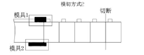
2.2. Electrode die-cutting method 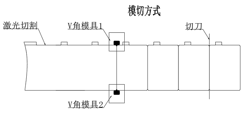
Oprional die cutting method which has edge trimming system
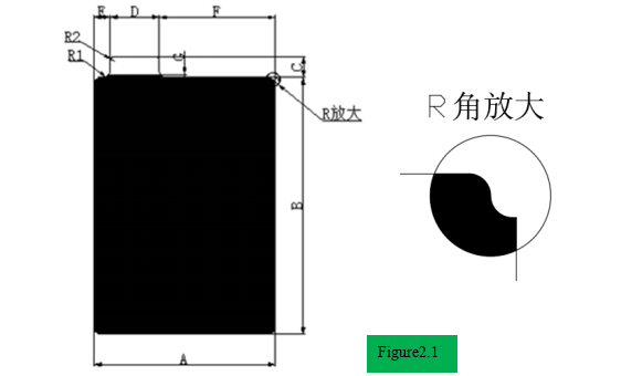
2.3 Product Size Information Confirmation Form
|
Model |
Cathode |
Anode |
Tab size |
Tab centence distance |
Fillet R |
||
|
L B |
W A |
L B |
W A |
||||
|
|
|
|
|
|
|
|
3 |
|
|
|
|
|
|
|
|
3 |
|
|
|
|
|
|
|
|
3 |
|
|
|
|
|
|
|
|
|
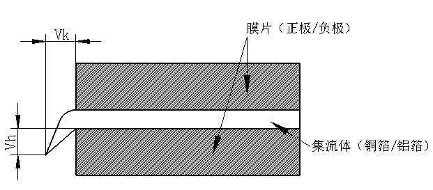
2.4Tab burr (see Figure 2.2)
(Hardware mold) Flat burr Vk (Metal burr)≤10um
Vertical Burr Vh (Metal Burr)≤15um
(Laser) Flat burr Vk (Metal burr)≤15um
(Laser) Vertical Burr Vh (Metal Burr)≤18um
Ⅲ、Equipment technical parameters
|
SN |
Item |
Parameters |
Remark |
|
1. |
Electrode length |
150-550mm(includes tabs) |
|
|
2. |
Electrode width |
80~265mm |
|
|
3. |
Inner diameter of feeding drum |
6 inch |
|
|
4. |
Outer diameter of feeding |
≤700mm(single roll) |
|
|
5. |
Equipment production speed |
Width(80-120) ≥120PPM Width(120-180) ≥90PPM Width(180-265) ≥60PPM |
|
|
6. |
Precision of electrode size |
±0.2mm |
|
|
7. |
Dissolved bead |
≤10um |
|
|
8. |
Heat Affected Zone |
Cathode≤100um Anode≤120um、 |
|
|
9. |
Leakage metal |
≤50um |
|
|
10. |
Knife life |
Use ≥ 1 million times after each mold repair Number of mold repairs ≥ 10 times, total lifespan ≥ 10 million times |
|
|
11. |
Uniformity of material receiving in the material box |
±0.5mm |
|
|
12. |
Equipment noise |
≤75 db(Distance machine:1M) |
|
|
13. |
Dimensional CCD detection |
Accuracy±0.15mm |
|
|
14. |
Defect CCD detection |
Misjudgment=0, Misjudgment ≤ 0.3% |
Related to the incoming material situation |
|
15. |
Equipment power supply |
AC400V,3 phase 50Hz Starting power ≤ 35Kw Operating power ≤ 20Kw |
|
|
16. |
Equipment air source |
Compressed air 0.5-0.6Mpa Gas consumption: 800L/min |
|
|
17. |
Equipment size |
About 9000×2100×2600(main machine) |
|
|
18. |
Color |
Standard warm gray 1C, color card required if requested by the customer |
|
|
19. |
Equipment weight |
About 8000Kg |
|
|
20. |
Qualified rate |
≥99.8 % |
|
|
21. |
Equipment failure rate |
≥1.5% |
|
|
22. |
Adapt to ambient temperature |
0-50 C° |
|
Ⅳ、Main component composition and function
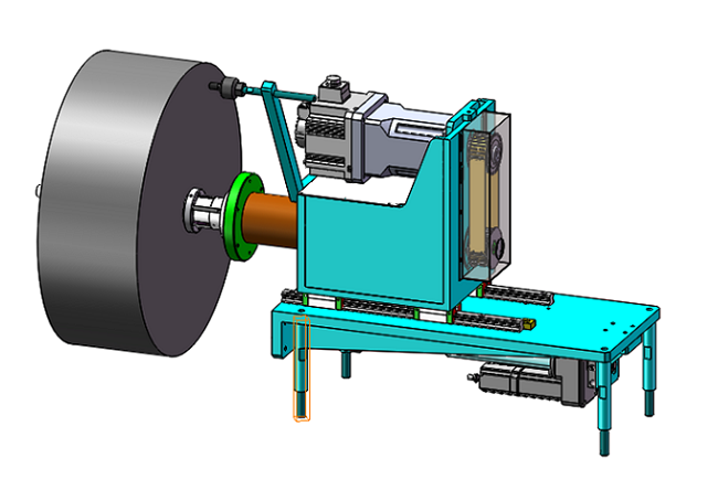
4.2.1 Unwinding module
Ø The unwinding mechanism adopts a set of 6-inch inflatable shaft structure, with the maximum diameter of the pole coil φ 700mm。
Ø The unwinding direction can be clockwise and counterclockwise;
Ø When loading, there is a fiber optic pen with a single character to assist in the positioning position of the pole coil loading;
Ø The unwinding mechanism is designed with unwinding correction, with a correction accuracy of ≤ ± 0.2mm and a correction stroke of ± 50mm;
4.2.2Taping mechanism
Ø Equipped with a coil material splicing platform and auxiliary marking lines for convenient manual splicing;
Ø There is a dust collection box at the cutting position, which is collected and cleaned by negative pressure extraction;
4.2.3 Tension mechanism:
Ø Swing roll speed synchronous control, the potentiometer detection signal is sent to PLC, and PLC controls the speed of servo motor;
Ø PLC+low friction cylinder+electrically controlled proportional valve to adjust tension, with a tension range of 10-150N and stable operation with tension fluctuation of ≤ 5%;
4.2.4.Process correction
Ø The process correction adopts a correction module, which has high correction accuracy and simple operation; The deviation correction compensation can be manually performed by clicking the module button to ensure the overall unwinding and deviation correction accuracy;
Ø Process deviation correction accuracy ≤ ± 0.1mm, deviation correction stroke ± 20mm;
4.2.5Laser die-cutting module:
1.250W fiber laser, pulse width adjustable, laser power stability<5%
2. Laser focal length adjustment accuracy ± 0.01mm
3.The repeated positioning accuracy of the galvanometer is ± 0.02mm
4.The minimum cutting R angle is greater than or equal to 1
5.Dual station laser cutting system
6.Accurate cutting size, non adhesive tab and non pole ear sides are installed with non cutting and missed cutting induction detection
7.During the unwinding process of the electrode piece, defects in the incoming material can be detected, which can detect the incoming tape and the machine's broken tape connection. After detecting the tape, normal cutting or skip cutting can be set. After skip cutting, the distance between the first tab position and the connection position can be set to improve material utilization
8.The entire cutting area is wrapped in a semi enclosed dust cover, and the laser cutting area has an independent two-stage closed structure. The dust generated during the cutting process is directly sucked away by a negative pressure vacuum cleaner, with a design wind speed of ≥ 20-25m/s (adjustable) and real-time monitoring of the wind speed
9.Laser protection: The observation window of the outer cover of the laser cutting studio adopts a laser protection plate
10.The waste generated by laser cutting is collected by the compactor, and the waste enters the compactor through the waste pipeline without affecting continuous cutting
11.Metal pipes are used for dust removal within 1 meter of the laser cutting position, while flame-retardant pipes are used for non-metallic pipes
12.The laser cutting control system has two cutting modes: equal spacing and unequal spacing, which can be freely switched and parameter set
13.With PSO control technology, it can accurately control the size of single point energy and output it at the designated position. With laser frequency conversion control, it can avoid over cutting or continuous cutting, and effectively control burrs and Heat-affected zone.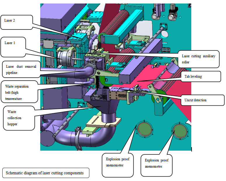
4.2.6.Material storage mechanism
Ø The use of servo+precision screw as a buffer for driving and tension coordination can ensure continuous uncoiling during die cutting, improve production efficiency, ensure stable tension, and ensure material drawing accuracy.
Ø The drum is made of lightweight materials, reducing the inertia moment of the storage drum, improving the drawing accuracy, and equipment stability.
Ø The roller is designed with carbon fiber.
Ø The control method adopts electronic cam overlay control.
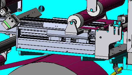
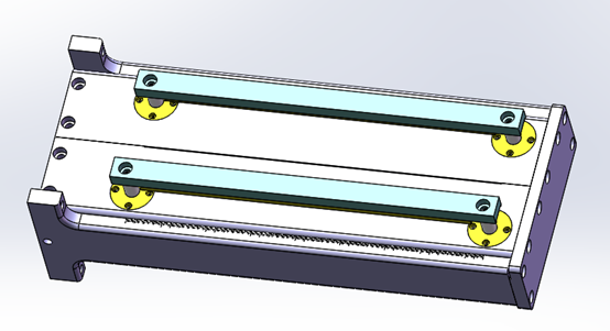
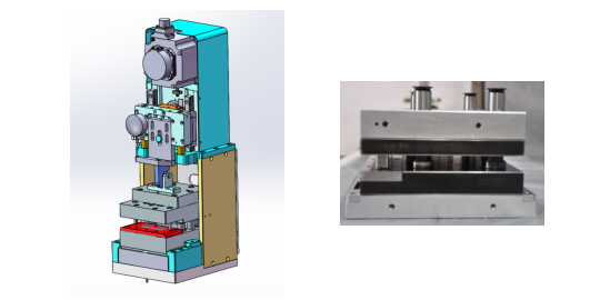
4.2.7.V-angle punching mechanism
Ø Two sets of V-angle punching and cutting forms are used to complete the forming of the tab;
Ø The mold punching module has an automatic deviation correction function, which detects the position of the pole pieces through sensors and adjusts the inner and outer positions of the mold in real time to ensure that the height and size of the pole piece punching are consistent; 2 color code sensors are used for positive side tape detection and skip cutting.
Ø Equipped with safety gratings, when the equipment is in operation, the grating equipment should be immediately shut down to prevent safety accidents from occurring;
Ø The bottom plate of the mold is made of marble material, which improves the flatness of the bottom plate and ensures that the mold does not deform after installation. The flatness is 0.01mm.
Ø Quick positioning is used between the mold and the mold base plate, making disassembly and assembly easy and the mold replacement time less than 0.5 hours;
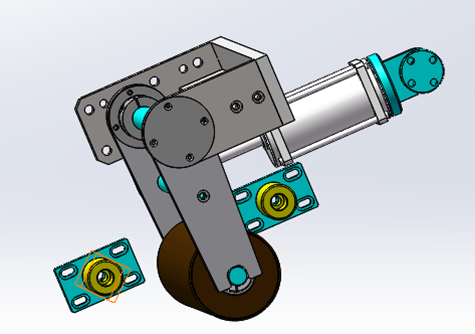
4.2.8. Pulling mechanism
Ø Patented servo pulling mechanism is adopted, with a maximum pulling speed of 60m/min and a pulling accuracy of ± 0.2mm
Ø The pulling roller is made of EPDM material and has a roller shaft. During normal operation of the equipment, no surface dust or particle accumulation occurs, ensuring that the surface of the electrode is flat and free from defects such as scratches.
Ø The upper and lower rollers are coated with adhesive and have a hardness of 90 degrees to maintain a snug fit.
Ø The pull-down material is a HV750 steel roller with thick hard chromium plating and precision grinding and polishing, with a roughness of Ra0.2
Ø The upper roller is compressed by a cylinder to ensure the accuracy of the pole size.
Ø Upper and lower driving mode of the cutting tool: servo motor drive with cam mechanism.
Ø Edge: Made of imported G5 tungsten steel
Ø The replacement time should not be longer than 0.5 hours.
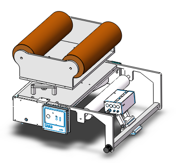
4.2.9.Conveyor belt mechanism
A:Upper belt:
Upper belt mechanism
Ø Driven by a servo motor, the driving motion curve is controlled by a uniformly accelerated bottom electronic cam, with the smoothest motion and the smallest impact.
Ø Drill a 3mm hole on the belt to generate negative pressure and suck the electrode piece through the belt hole
Ø The leather has an automatic brush cleaning function, and the belt is made of a special material with a 1.5mm thick PU bottom PVC.
Ø Integrated size detection CCD and dust removal function on the upper surface.
B Lower belt:
Ø Driven by a servo motor, the driving motion curve is controlled by a uniformly accelerated bottom electronic cam, with the smoothest motion and the smallest impact.
Ø A 3mm hole is drilled on the 1.5mm thick belt to generate negative pressure through the belt hole, which attracts the pole pieces and divides them into multiple pieces.
Ø The leather has an automatic brush cleaning function, and the belt is made of special material with a PU surface and PVC bottom.
Ø Integrated electrode cutting and lower surface dust removal functions on the top.
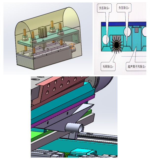
4.2.10.Brushing mechanism
Brushing powder to clean the surface of the electrode can timely remove waste materials, dust, etc. generated during the punching process. Through the dust collection and filtration system, it ensures that the dust does not diffuse to the surrounding area of the equipment.
Ø Dust removal system noise:≤75db
Ø The cleaning device adopts centralized dust removal.
Ø A powerful dust removal mechanism combining ion blowing and suction is used for dust removal.
Ø The powder brushing mechanism is equipped with 10000Gs of strong magnetism for dust removal containing magnetic dust
Ø Clean the dust on the surface of the electrode by suction at the unwinding point.
Ø Die-cutting generates dust by suction through the lower hollow and negative pressure.
Ø Under the cutting knife, the dust is sucked away by suction.
Ø Clean stubborn dust on the electrode with a brush.
4.2.11.Electrode receiving device
The electrode pieces are automatically fed into the material box through the belt conveyor line, and the material box is equipped with automatic lifting and full material alarm devices. Equipped with polar buffer mechanism.
Ø The electrode pieces after punching are automatically stacked inside the material box, and the stacking process does not collide with the edges of the electrode pieces.
Ø The electrode pieces of the material box are neat: ≤ ± 0.5mm. The electrode plate does not touch the edge of the material box during the material falling process.
Ø Method of removing polar plates: using a conveyor belt to discharge and adsorb onto the belt.
Ø Electrode stacking height control: The stepper motor controls the number of stacked electrode pieces.
Ø Install a mandatory emergency stop button at a reasonable position in the discharge area of the electrode.
Ø Defective electrode plates are automatically discharged, and other anti band designs such as giving an alarm for 3 consecutive pieces of defective size and stopping the machine for 5 consecutive pieces are provided.
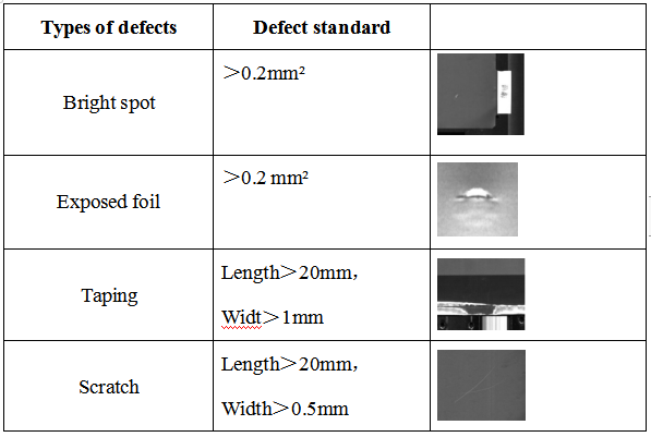
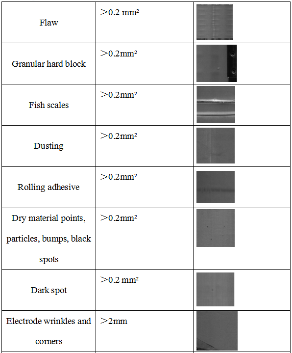
4.2.12.Defect detection
Ø When the electrode passes through the roller, a linear array camera is used to scan the surface of the electrode row by row and concatenate it into a complete image. A specific image detection algorithm is used to analyze and calculate the characteristics of the image. Based on the pre-set indicators of each defect parameter, the software outputs a pass/fail signal, and the defective electrode is automatically removed by the defective product removal mechanism.
Ø Using two 16 K linear array black and white high-speed industrial cameras and a high brightness linear light source with an effective length of 400mm, the electrode width can be detected to be 400mm.
Ø All defect data detected on the front and back sides of the CCD monitoring electrode can be directly exported to a CSV document. Test standard parameters (actual process parameters shall prevail), with a missed judgment of 0, a false judgment of ≤ 0.5%, and a grayscale difference of no less than 30.
Ø Artificial intelligence identifies defective products and categorizes them.
4.2.13.CCD Size detection mechanism
Ø By taking photos of the electrode plate using CCD, the height of the electrode ear strip and exposed foil can be detected, including the length, distance from the electrode ear to the edge, width, and angle of the electrode plate. The detection accuracy is ± 0.1mm, with a missed judgment of 0 and a misjudgment of ≤ 3 ‰.
Ø Using an array industrial camera for detection.
Ø Adopting a backlight source detection scheme, the backlight source illumination scheme can improve detection accuracy;
Ø Before size inspection, there is a pressing mechanism to flatten the electrode plate to prevent detection errors caused by poor adsorption;
Ø The size inspection items include: electrode width, height, angle, electrode shoulder width, electrode tape material, etc.
4.2.14.Control system
Composed of 1 set of PLC, 1 15 inch touch screen, and other electrical components; Adopting bus connection reduces the number of cables and makes the connection of the electrical box more concise and aesthetically pleasing.
4.2.15.Rack cover
Ø The rack is made of high-strength square steel pipes welded and the surface is painted.
Ø The equipment is equipped with dustproof covers made of aluminum alloy or sheet metal and organic glass.
Ø The top of the outer cover is equipped with an FFU filtering unit to supply air to the inside of the machine, which, in conjunction with a vacuum cleaner, circulates and flows air inside the machine.
Ø The internal cleanliness of the equipment cover should be ≥ 100000 levels. 
Ⅴ、List of Main Equipment Accessories
5.1 List of Main Accessories:
|
SN |
Main configuration |
Brand |
Origin |
|
1 |
PLC control system |
Ouchui |
UK |
|
2 |
Deviation |
Puliyuan/Bat |
China |
|
3 |
Touch Screen |
Weinview |
China |
|
4 |
Servo motor |
ESTUN |
China |
|
5 |
Tension controller |
Fujikura |
Japan |
|
6 |
Pneumatic components |
SMC、Airtac |
Japan、Taiwan |
|
7 |
Screw guide rail |
上银Hiwin |
Taiwan |
|
8 |
Bearing |
NSK |
Japan |
|
9 |
Switching appliances |
Schneider、Panasonic |
Germany、Japan |
|
10 |
Photoelectric sensor |
OmRon、Panasonic、Baomeng, Giant Dragon |
Japan、China |
|
11 |
CCD |
Haikang |
China |
5.2 List of Vulnerable Parts:
|
SN |
Item |
Specification |
Remark |
|
1 |
Photoelectric switch |
EE-SX671A |
OMRon |
|
2 |
Intermediate relay |
MY2J-12VDC |
Schneider |
|
3 |
Button Switch |
φ22 |
Schneider |


 cindy@tmaxcn.com
 David@battery-equipments.com
 Wechat 13506084915