 English▼


- Battery Manufacturing Equipment
- Battery Laboratory Assembly Equipment
- Battery Pack Assembly Equipment
- Sodium Ion Battery Manufacturing Equipment
- Solid State Cell Production Line
- Dry Electrode Assembly Equipment
- Supercapacitor Assembly Equipment
- Perovskite Solar Cell Lab Equipment
- Li ion Battery Materials
- Ni / Al / Cu Metal Foam
- Customized Electrode
- Cathode Active Materials
- Anode Active Materials
- Coin Cell Parts
- Lithium Chip
- Cylindrical Cell Parts
- Battery Current Collectors
- Battery Conductive Materials
- Electrolyte
- Battery Binder
- Separator and Tape
- Aluminum Laminate Film
- Nickel Strip/Foil
- Battery Tabs
- Graphene Materials
- Cu / Al / Ni / Stainless steel Foil
- Battery Laboratory Equipment
- Li ion Battery Tester
- Battery Safety Tester
- Material Characterization Tester
- Rolling Press Machine
- Electrode Mixer
- Coin Cell Crimping Machine
- Coin Cell Electrode Disc Punching
- Pouch Cell Sealing Machine
- Pouch Cell Stacking Machine
- Pouch Cell Forming Machine
- Pouch Cell Ultrasonic Welder
- Pouch Cell Electrode Die Cutter
- Cylinder Cell Sealing Machine
- Cylinder Cell Grooving Machine
- Electrode Slitting Machine
- Cylinder Cell Winding Machine
- Cylinder Cell Spot Welding Machine
- Electrolyte Filling
- Type Test Cell
- Other Battery Making Machine
- NMP Solvent Treatment System
- Vacuum Glove Box
- Coating Machine
- Lab Furnaces
- Ball Mill
- Laboratory Press
- Laboratory Equipment
- Press Equipment
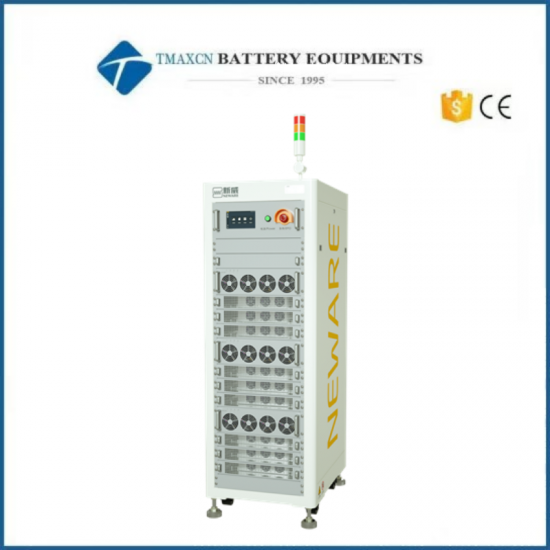
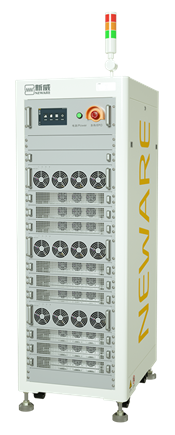
100V30A 16 Channel Battery Charging And Discharging Tester
Model Number:
TMAX-16C-100V30ACompliance:
CE certificateWarranty:
Two Year Limited Warranty With Lifetime SupportPayment:
T/T, Credit Card, Paypal, LC, Western UnionDelivery Time:
3 Days
100V30A 16 Channel Battery Charging And Discharging Tester
Specifications
|
1. Material code |
CE-6016n-100V30A-H |
|
|
2、Channels information |
||
|
1. Channels quantity |
Channels quantity in one unit |
16 |
|
2. Main channel |
Channel feature |
Constant current source and constant voltage source dual closed loop control |
|
|
Channel control mode |
Independent control |
|
|
Channel parallel connection |
Support max 4 channels parallel mode. Pulse and SIM tests will be disabled in channels parallel mode.
|
|
3、Power grid side parameters |
||
|
1.Input power |
|
AC380V±15% 50/60±5Hz |
|
2.Power factor |
|
≥99%(Full load) |
|
3.THDi |
|
≤5%(Full load) |
|
4.Input resistance |
|
≥1MΩ |
|
5.Input power |
|
56.5KW |
|
6.Input current |
|
85.8A/single |
|
7.Overall system efficiency(Max) |
|
90% |
|
8.Noise |
|
≤65dB |
|
9.Voltage and current sampling |
|
Four-wire connection(same port for charging and discharging) |
|
10.Power control module type |
|
MOSFET |
|
11.Input power wiring method |
|
Three-phase-five wire system |
|
12.Power input protection |
|
Anti-surge, anti-silos, anti over or under frequency, anti over or under voltage, anti phase absence, etc. |
|
4、Functions and performances |
||
|
1. Voltage |
Output range |
Charge:0V~100V |
|
|
|
Discharge:3V~100V |
|
|
Min discharge voltage |
3V |
|
|
Accuracy |
±0.02% of FS |
|
|
Resolution |
24bit |
|
2. Current |
Output range |
0.15A~30A |
|
|
Accuracy(independent range) |
±0.05% of FS |
|
|
CV cut-off current |
30mA |
|
|
Resolution |
24bit |
|
3. Power |
Single channel output power |
3KW |
|
|
Whole machine output power |
48KW |
|
4. Time |
Current response time |
≤3ms |
|
|
Current conversion time |
≤6ms |
|
|
Min. step time |
0.1s |
|
5. Charge/Discharge modes |
Charge/Discharge modes |
CCC, CVC, CC-CVC, CPC |
|
|
|
CCD, CVD, CPD, CRD |
|
|
Cut-off condition |
Voltage, Current, ΔTime, Capacity, -ΔV |
|
6. Simulation |
Charge |
Current, Power |
|
|
Discharge |
Current, Power |
|
|
Switch |
Support continuous switching between charge and discharge |
|
|
Cut-off condition |
Time, step line |
|
|
Steps file lines |
1,000,000 |
|
7. Pulse Mode |
Charge |
Current ,power |
|
|
Discharge |
Current, Power |
|
|
Min pulse |
100ms |
|
|
Pulse counts |
Up to 32 |
|
|
Charge and discharge switch |
supported |
|
|
Cut-off condition |
Voltage, ΔTime |
|
8. DCIR |
|
DCIR by calculation |
|
9. Safely protection |
Software protection |
Power off data protection |
|
|
|
Offline mode function |
|
|
|
Safety protection conditions can be set, including:voltage lower limit ,voltage upper limit ,current lower limit ,current upper limit ,delay time, etc. |
|
|
Hardware protection |
Anti-reverse connection, over-voltage, over-current, over-temperature, etc. |


 David@battery-equipments.com

