 English▼


- Battery Manufacturing Equipment
- Battery Laboratory Assembly Equipment
- Battery Pack Assembly Equipment
- Sodium Ion Battery Manufacturing Equipment
- Solid State Cell Production Line
- Dry Electrode Assembly Equipment
- Supercapacitor Assembly Equipment
- Perovskite Solar Cell Lab Equipment
- Li ion Battery Materials
- Ni / Al / Cu Metal Foam
- Customized Electrode
- Cathode Active Materials
- Anode Active Materials
- Coin Cell Parts
- Lithium Chip
- Cylindrical Cell Parts
- Battery Current Collectors
- Battery Conductive Materials
- Electrolyte
- Battery Binder
- Separator and Tape
- Aluminum Laminate Film
- Nickel Strip/Foil
- Battery Tabs
- Graphene Materials
- Cu / Al / Ni / Stainless steel Foil
- Battery Laboratory Equipment
- Li ion Battery Tester
- Battery Safety Tester
- Material Characterization Tester
- Rolling Press Machine
- Electrode Mixer
- Coin Cell Crimping Machine
- Coin Cell Electrode Disc Punching
- Pouch Cell Sealing Machine
- Pouch Cell Stacking Machine
- Pouch Cell Forming Machine
- Pouch Cell Ultrasonic Welder
- Pouch Cell Electrode Die Cutter
- Cylinder Cell Sealing Machine
- Cylinder Cell Grooving Machine
- Electrode Slitting Machine
- Cylinder Cell Winding Machine
- Cylinder Cell Spot Welding Machine
- Electrolyte Filling
- Type Test Cell
- Other Battery Making Machine
- NMP Solvent Treatment System
- Vacuum Glove Box
- Coating Machine
- Lab Furnaces
- Ball Mill
- Laboratory Press
- Laboratory Equipment
- Press Equipment
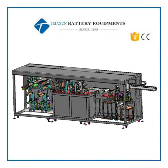
Automatic Prismatic Battery Die Cutting Machine For Lithium Battery Production
Model Number:
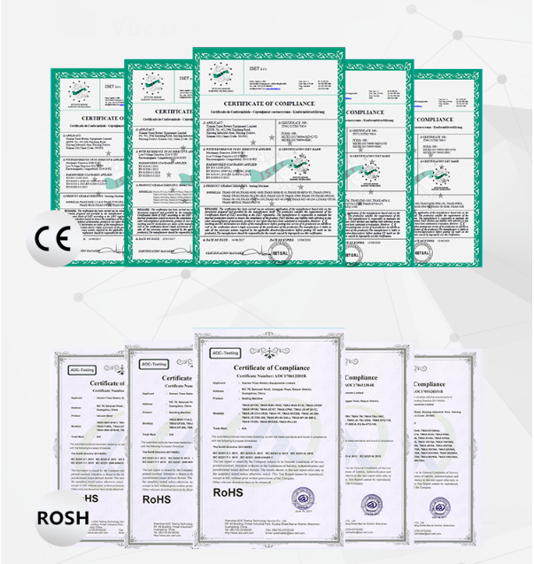
TMAX-YK-DP400-L01BCompliance:
CE compliantWarranty:
Two Year Limited Warranty With Lifetime SupportPayment:
T/T, Credit Card, Paypal, LC, Western UnionDelivery Time:
3 Days
Automatic Prismatic Battery Die Cutting Machine For Lithium Battery Production
1、 Equipment introduction
1. Equipment functions
* unwinding function (two unwinding mechanisms are adopted, and the servo motor independently controls the automatic unwinding);
* deviation correction function (correcting the deviation of the unwinding mechanism and the electrode is being transported before punching);
*belt tension control system (belt tension is independently controlled by two buffer modes, which can reduce belt jitter in the process of high die cutting);
* the metal concave convex die is used to complete the forming of the pole ear (tungsten steel die is used, with high service life and small punching Burr);
* dust removal of equipment rollers (dust absorption of pulling rollers);
* before die cutting, the electrode is brushed and vacuumed;
* single chip cutting function (adopt servo control crankshaft drive structure to complete cutting, adopt tungsten steel mold, with high service life and small punching Burr);
* single electrode conveying function (three vacuum belts are used to convey the electrode, dust removal on both sides of the electrode and screening of defective products are carried out during the conveying process);
* dust removal on both sides of the electrode (wool felt and negative pressure dust collection by default; non-contact electrostatic dust removal device is reserved) this dust removal method is optional;
*double CCD detection and labeling of electrode surface defects (CCD detects both sides of the electrode, the labeling machine labels the unqualified products after detection, and pulls this section through when the pole ear is formed; the equipment does not have this function by default, and the installation position is reserved) this function is optional;
l color code detection of defective products (the sensing electrode has a defective label, and the electrode device automatically screens out defective products);
*single electrode size CCD detection (for each electrode overall size detection, the equipment will automatically screen out defective products);
* electrode collection function (electrode counting function is installed in the material box, with the function of sorting electrodes, and the electrodes are collected neatly in the material box);
*the cartridge case conversion and conveying function (the cartridge is installed on the turntable, and the cartridge case is automatically converted; the manipulator extracts the cartridge case and connects the material line) the cartridge case can be shared with the lamination machine;
2. Equipment principle
The principle of continuous feeding of polar coil, controlling die punching and polar impulse through the mode of electronic cam, and controlling unequal distance by servo traction.
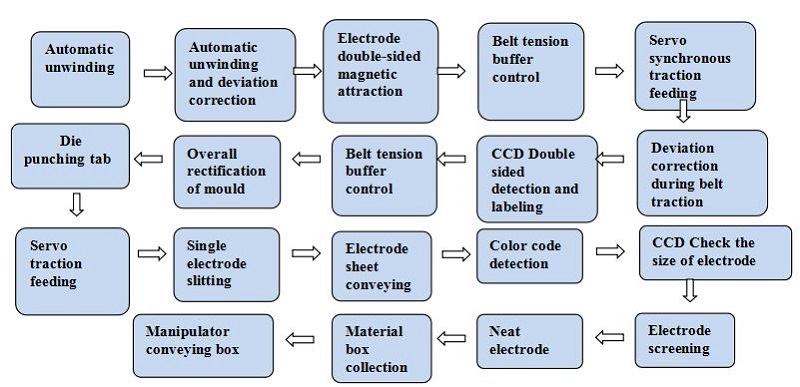
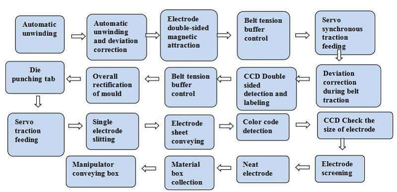
3. Equipment action process
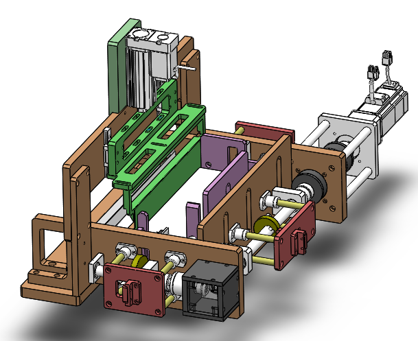
4. Overall structure
1) Size:4200mm L;W:1280mm;H:2050mm。
2) Weight:1.85T
3) Overall structure diagram
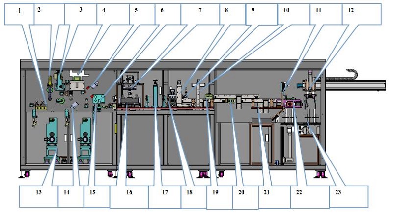
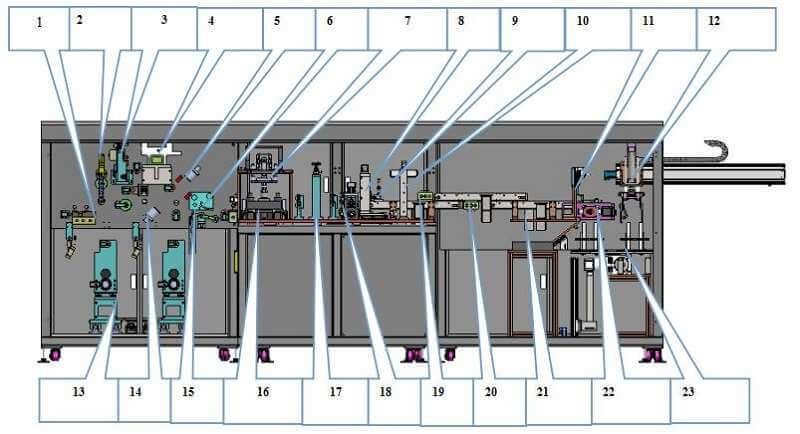
1. 上料接料台:Feeding and receiving platform
2. 张力缓存机构:Tension buffer mechanism
3. 滚轮牵引机构:Roller traction mechanism
4. 过程纠偏组件:Process correction component
5. CCD检测:CCD Testing
6. 贴胶机:Glue applicator
7. 极耳成型模切组件: Tab forming die cutting assembly
8. 裁切机构:Cutting mechanism
9. 色标传感器:Color code sensor
10. CCD检测机构: CCD detection mechanism
11. 次品剔除机构:Reject mechanism
12. 机械手抓取机构:Manipulator grabbing mechanism
13. 自动放卷纠偏装置: Automatic unwinding and deviation correction device
14. CCD检测:CCD Testing
15. 缓存机构:Cache mechanism
16. 模具冲切机构:Die punching mechanism
17. 转型调节机构:Transformation adjustment institution
18. 滚轮牵引机构:Roller traction mechanism
19. 除尘机构:Dust removal mechanism
20. 除尘机构:Dust removal mechanism
21. 次品收集盒:Defective product collection box
22. 整齐料盒极片机构:Neat material box electrode mechanism
23. 转化料盒机构:Conversion box mechanism
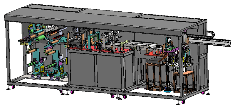
4) Equipment appearance diagram

4、Function introduction of equipment components
4.1. Automatic feeding device
 Max Dia:φ700mm;
 Max weight:150kg;
Sleeve inner diameter:150.2±0.5mm;
Unwinding and feeding mode: feeding is directly operated by logistics docking trolley or manual;
The unwinding mechanism adopts the inflatable shaft structure, and both ends of the inflatable shaft are equipped with rolling bearings, which is firm in structure;
It is equipped with coiling belt connecting platform and auxiliary marking line, which is convenient for manual belt connecting;
There is a permanent magnet bar with 40000gs behind the receiving table to remove iron from the front and back of the electrode;
Dust collection by double-sided roller brush of polar piece before die cutting;
With pressing device before die cutting;
The servo system is used to control the synchronous unwinding to keep the tension stable;
The adjustable range of tension is 0-150N, and the accuracy is±10%;
Before and after the upper and lower materials, the reeling shaft wobbles≤5mm;
Distance from the end face of the winding shaft to the outside of the protective cover≤250mm;
With safety protection design;
The deviation correction system adopts high-precision CCD deviation correction sensor to control the opposite side and improve the deviation correction accuracy±0.2mm.
4.2. Belt tension control system
 The unwinding tension control of the material belt is composed of two mechanisms;
 The unwinding part of the air expansion shaft is controlled by the swing of the low friction cylinder to control the tension during the unwinding process;
During die punching, the belt swings up and down, and the servo motor pulls the screw rod to compensate. For example, when the die rises and falls, the servo motor quickly pulls the length of the pole piece to ensure the tension in the process of pole piece conveying;
The swing part adopts high-precision proportional valve, high-precision potentiometer and low friction cylinder to control the feeding synchronously;
The screw rod is controlled by servo analog quantity, and the tension can be set according to the size of the pole piece;
4.3. Tab punching and forming device

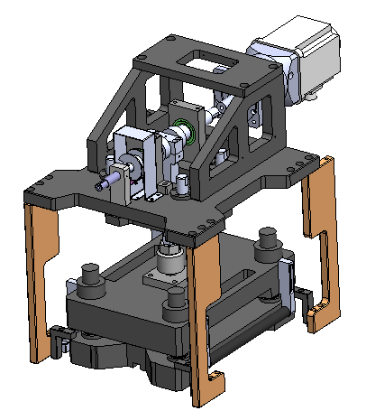 Adopt the metal concave convex die punching form to complete the forming of the tab
 The upper and lower die punching adopts the scissor point contact mode;
The servo driven crankshaft is used to complete the high-speed punching action of the die, and the pole piece is free of damage, powder dropping, sharp corners and other defects during the slicing process;
The disassembly and installation of the die are simple, and the width of the pole piece is easy to adjust. It can meet the different sizes of pole pieces within a certain range, and the change time is less than 1 hour;
A funnel-shaped waste collection device is installed under the mold, and the waste generated after punching and cutting can be immediately sucked into the funnel device and then collected into the waste recycling box (cleaning once per shift, cleaning time ≤ 5min);
The upper die of the die is equipped with positive pressure blowing cooling function to improve the punching life of the die;
The punching mechanism is equipped with safety protective optical fiber and safety protective cover;
The system adopts high-precision CCD deviation correction sensor to improve the deviation correction accuracy,≥0.2mm;
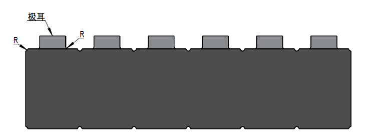
Parameters of electrode after punching:

4.4.Belt traction device
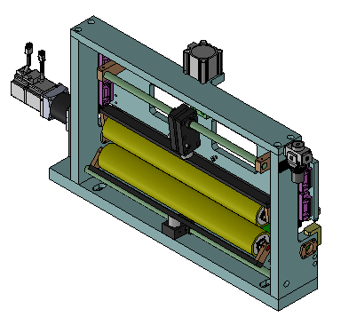
 The material belt traction and conveying process consists of two sets of traction roller assemblies
 The first set of high-speed control reeling process conveying synchronization;
The second set of high-speed control punching center pole piece conveying synchronization;
Adopt servo control unequal distance feeding function;
There is a tan guide wheel in front of the traction roller to prevent the tab from being discounted after die cutting. The guide wheel can be adjusted easily when changing the model;
The two rollers are directly equipped with powder absorbing rollers to remove the dust accumulated during the traction of the rollers;
The pressing roller is compressed automatically by air cylinder, which is convenient for threading.
4.4Cutting mechanism
In the process of pole slice cutting, there is pre pressing function in the front and traction roller in the back to ensure the ductility of pole slice before cutting and the dimensional accuracy of pole slice powder cutting;
after cutting, the equipment is equipped with induction optical fiber to prevent the pole knife from being mistaken for multiple pieces of waste;
the lower cutter is installed with vacuum to absorb dust;
The embedded tungsten steel knife is adopted to reduce the maintenance and replacement cost
Cutting has counting function.
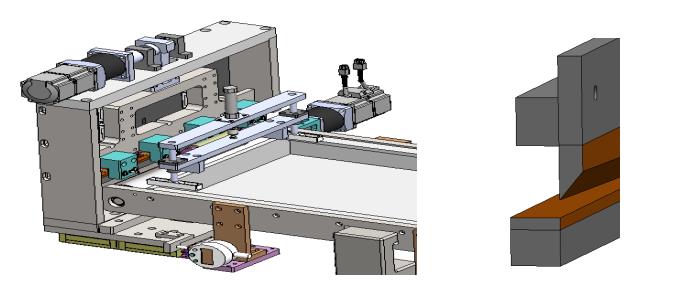
5.Electrode correction function in feeding box
during the operation of the electrode, the servo motor drives the sorting mechanism to correct the electrode;
After correction, the electrode are stacked in the material box to ensure that the electrode in the material box are neat;
The material box has a counting function, and the pole pieces are free of damage, crimping, bending, scratches and other defects during operation and stacking;
When the electrode in the material box is filled, it will automatically switch to the buffer mechanism to receive the material.
5、Dust removal device (optional)
1) Wool wheel, negative pressure to collect dust
the equipment adopts wool wheel and negative pressure dust removal method, which has good dust removal effect, high efficiency and low cost;
When the electrode passes through the inlet end of the cleaning head, roll the driving brush to sweep the powder to remove the dust on the surface of the electrode;
Subsequently, the pole piece receives internal negative pressure wind to absorb drift dust and dust on the brush wheel;
Dust is collected in the negative pressure fan, which is easy to clean (once a month, cleaning time ≤ 5min).
1) Non contact dust removal
adopt the non-contact dust removal method of high-pressure ion wind, which has good dust removal effect, high efficiency and high cost;
When the electrode passes through the inlet end of the cleaning head, the ionization cloud here and the static electricity on the coil surface are removed;
Then, the electrode is affected by the turbulent air flow generated by the internal blowing and vacuum air flow of the cleaning head device;
The effect of turbulent air flow leads to high-frequency fretting of the electrode;
The combined action of high-frequency fretting and turbulent air flow of the electrode breaks the air interface layer on the surface of the pole piece, and at the same time, the pollutants released by the interface layer are sucked into the vacuum air flow;
When the electrode leaves the cleaning head, the pole piece will pass through another ion cloud to prevent secondary pollution on the surface of the electrode.
6.Design features
|
Features |
Advantages |
|
Non contact cleaning |
Avoid the risk of marks and damage on the surface of the electrode, and at the same time, do not affect the tracking detection of the position of the electrode on the belt |
|
Electrostatic control integration |
Neutralize static electricity, optimize cleaning performance, and effectively pre polarize the secondary pollution on the surface of the sheet |
|
Unique "fixed port" system |
The pipeline connection of the cleaning head is fixed, and the installation of the cleaning head is easier |
|
Air volume balance |
The deviation value between blowing volume and vacuum air flow can be completely controlled |
|
Automatic vacuum control |
Reduce the frequency of manual adjustment by operators. Automatically maintain the best cleaning effect |
|
Lossless parts |
Lower operation cost |
|
Silent operation |
No health and safety problems caused by noise |
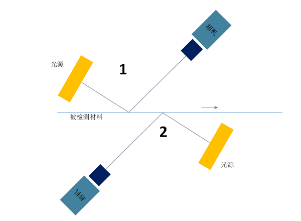
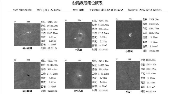
7.Schematic diagram of CCD detection and labeling (an optional device)
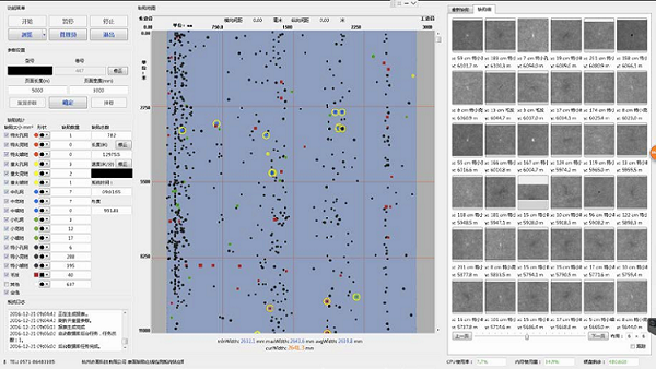
8. System functions
l Intelligent classification: using machine learning and artificial intelligence technology, self-learning and automatic classification can be carried out according to the user's definition of defect category;
l PostgreSQL:Adopt the most advanced open source database to store defect images, such as defect location, size and other information;
l Automatic archiving: defect data can be automatically backed up to external devices or systems according to user settings
l Diversified reports: provide reports on test results and statistical data in the form of tables and graphs
l Surface evenness analysis: display the surface evenness of materials in real time with digital;
l practical and convenient operation interface: it can eliminate and mark serious defects and other practical functions, which is convenient for operators to operate;
l IO interface: provide input and output signals such as alarm, paper break, roll change, start and stop;
l Factory interface: Based on Windows operating system, it can connect with other systems and equipment of customers through tcp/ip, Ethernet, OPC and other interfaces;
l Remote access maintenance: under the condition that the equipment is connected to the Internet, the system can be upgraded and maintained through Internet remote access;
l Technical support: 7 x 24-hour network and hotline support
l Detection system interface
l report viewing interface
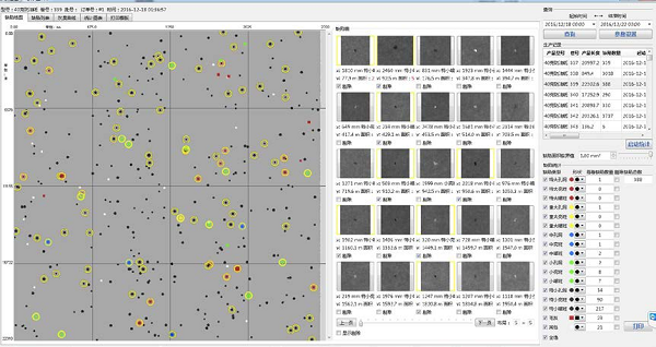
l defect elimination Report
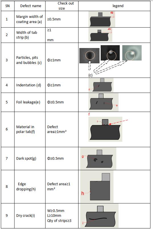
l main defect detection accuracy index table
Labeling machine device:
Equipped with a set of labeling machine, the pasting speed matches the cutting speed, and the labeling center line and the inner edge distance of the pole piece can be adjusted, with an accuracy of ± 2mm;
Label size: 12mm wide and 14mm long, which can be customized by users.
A、Size and specification of incoming materials
|
SN |
Item |
Spec |
Remark |
|
1 |
Feed width |
300-420mm(including tab) |
|
|
2 |
Incoming material thickness |
Cathode:9-200μm;Anode:9-200μm |
|
|
3 |
Inner diameter of discharging drum |
6inch φ150.2mm |
|
|
4 |
Applicable system |
Lithium iron phosphate, lithium cobalt oxide, lithium manganate, ternary materials, graphite and other battery and capacitor slurry systems |
|
|
5 |
Outer diameter of electrode sheet |
≤φ700mm |
|
|
6 |
Coating method |
Continuous coating |
|
|
7 |
Incoming coating width error |
≤±2mm |
|
B、Production incoming material requirement
l Evenness error of incoming winding end face:±5mm;
l Serpentine error:X±2mm/m;
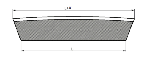
l Electrode wave:X±5mm/m;
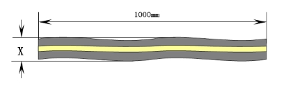
l ensure the service life of the mold, and the change of material thickness at the cutting position of the mold is less than 10 μ m
C、Equipment production process
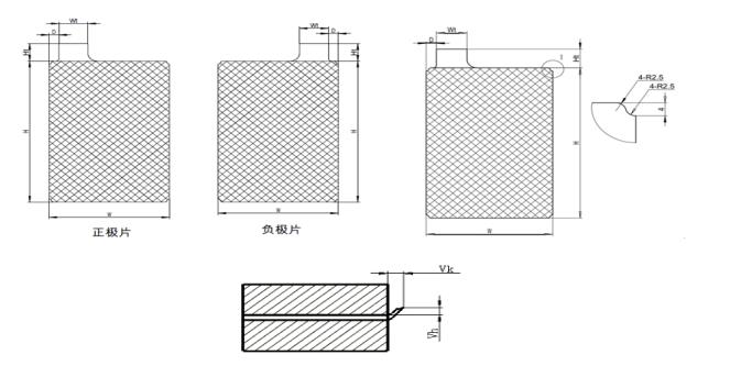
|
Size range and accuracy of electrode after punching |
||||
|
SN |
Item |
Size(mm) |
Accuracy |
Remark |
|
1 |
Electrode W |
40~110 |
±0.2mm |
|
|
2 |
Electrode H |
60~160 |
±0.25mm |
|
|
3 |
Electrode Ht |
10~30 |
±0.2mm |
|
|
4 |
Electrode Distance |
5~20 |
±0.25mm |
|
|
5 |
Electrode Wt |
6~65 |
±0.2mm |
|
|
6 |
Burr vh |
≤7um |
|
|
|
7 |
Burr vk |
≤25um |
|
|
D、Technical index parameters of equipment
|
SN |
Item |
Spec |
|
1 |
Punching method |
Die punching |
|
2 |
Service life of die for tab and mark hole |
Negative electrode mold 1million times / grinding, mold grinding times ≥ 10 times 800000 times / grinding of positive mold, and the number of mold grinding ≥ 10 times Total service life of die-cutting knife after repair: ≥ 10million times |
|
3 |
Loading condition |
Manual roll loading function, the equipment can realize the residual material detection and alarm function It can distinguish between roll termination tape and tape splicing tape (different tape colors) |
|
4 |
Electrode deviation correction device |
The deviation correction accuracy is guaranteed to be 0.1mm on the premise that the material has no edge defects |
|
5 |
Electrode tension control |
Tension control accuracy<10% |
|
6 |
Stamping die |
SKD-11 + Imported alloy tungsten steel |
|
7 |
Dust removal device |
Dust removal on both sides of electrode after punching |
|
8 |
Magnet adsorption |
≥40000GSPermanent magnet rod |
|
9 |
CCD testing |
A set of CCD detection device is set on the front and back of the pole piece respectively |
|
10 |
CCD configuration |
8K camera 2 pcs,light source 2 pcs |
|
11 |
CCD Detection scope |
Max450mm(Coating width:400mm) |
|
12 |
CCD Test items |
Coating defects of standard lithium battery pole pieces such as exposed foil, dry material, dark spots, scratches, foreign matters, etc |
|
13 |
CCD Test items |
Transverse0.1mm、Portrait:0.1mm (Best detection state)(80m/min, cutting speed) |
|
14 |
CCD Other functions of the system |
Alarm output or labeling can be provided according to the size, type, density, cutting position and periodicity of defects. All detected defect data are stored in SQL database in each volume, or exported to the factory's information management system or various standard databases. Reportranger software can automatically or manually output various automatic reports of production and quality management according to needs, and can be set according to customer needs, accurately label the edges of materials, and cooperate with downstream processes to better find and deal with various defects. |
|
15 |
Labeling mechanism |
Label cutting and labeling mechanism; The labeling speed matches the pulling speed, and the labeling machine is located at the tab |
|
16 |
MES system |
All process equipment used shall have MES system interface |
|
17 |
Efficiency |
≥120ppm,Rate of mobilization≥95%,Qualified rate≥98% |
|
18 |
Quick change time |
The model of a single replacement mold does not exceed 1person*1H |
|
19 |
Other requirements |
1. A. the update of equipment program can be realized through remote; b. Hardware (Electrical) detection; The notebook with network is configured in the remote mode, and the software required for remote control is installed on the notebook. The equipment manufacturer realizes remote control with the equipment through the notebook. For the sake of data security, a monitoring program will be installed on the notebook to monitor all data exchanged through the notebook. 2. Hierarchical management of equipment: at least three levels are required. The highest level is the management authority of the equipment, which can realize any operation on the equipment and reset all passwords. The second level is to change all parameters of the equipment and realize equipment operation. The lowest level is equipment operation and change some operations. Equipment operation time recording function, recording contents need to be divided into automatic operation time, standby time, manual operation time and failure time. Machine time is defined as the time when the equipment is turned on but no operation is carried out, and fault time is defined as the time before the equipment fails and the error message is not eliminated, and the time when the emergency stop button is pressed; Automatic operation and manual operation are the normal operation time of the equipment without any fault and error, which can be distinguished according to the selected operation mode. At least 2 days of operation records shall be kept on the equipment. The operation records shall be packaged and sent to MES system or other management system once a day, and uploaded by FTP. The uploaded files shall be in CSV format. Recording function of equipment parameter changes. |
|
20 |
Vibration standard |
The vibration intensity shall meet the iso-2372 international standard for equipment vibration (vibration intensity ≤ 0.45mm/s) |
|
21 |
Safety device |
1. Punching mechanism, cutting mechanism and other mechanisms are equipped with safety protection door to prevent operators from entering and door opening protection circuit design and emergency stop function, and there are safety warnings 2. The fault alarm indicator is a three color lamp post and buzzer alarm, and there is a record display on the touch screen panel |
E、Main components of equipment
|
SN |
Name |
Brand |
|
1 |
PLC |
Panasonic |
|
2 |
touch screen |
Weinview |
|
3 |
Frequency converter |
Schneider |
|
4 |
servo motor |
Panasonic |
|
5 |
Stepper motor |
Leisai |
|
6 |
Cylinder and pneumatic components |
SMC |
|
7 |
Linear guide rail, screw rod |
THK |
|
8 |
sensor |
Keens |
|
9 |
Bearing |
NSK |
|
10 |
Solenoid valve |
SMC |
|
11 |
Temperature Controller |
OMRON |
|
12 |
Automatic control valve |
Shanghai Ziyi |
|
13 |
Vacuum gauge / pressure gauge |
SMC |
|
14 |
Low voltage electrical components |
Schneider |
|
15 |
CDD Testing |
Chixiao Technology |
|
16 |
Mold |
Wei Sheng |
|
17 |
Die guide post |
MISUMI |
|
18 |
Optical fiber |
Panasonic |
|
19 |
Magnetic switch |
SMC |
|
20 |
Low voltage electrical components |
Schneider |
F、Equipment use environment
|
SN |
Item |
Unit |
Spec |
Remark |
|
|
1 |
Whole line power |
Kw |
15 |
380V, 3phase |
|
|
2 |
compressed air |
Pressure |
MPa |
0.5~0.8 MPa |
|
|
|
|
consumption |
L/min |
50 |
|
|
3 |
Vacuum |
vacuum degree |
KPa |
/ |
|
|
|
|
consumption |
m3/h |
/ |
|
|
|
|
consumption |
m3/h |
/ |
|
|
4 |
nitrogen |
Pressure |
MPa |
/ |
|
|
|
|
consumption |
m3/h |
/ |
|
|
5 |
Tap water consumption |
m3/h |
/ |
|
|
|
6 |
Process cooling water |
Temperature |
℃ |
/ |
|
|
|
|
consumption |
m3/h |
/ |
|
|
Note: the parameters involved in the equipment must be filled in, and the parameters not involved can be filled in with "/" or "-"。 |
|||||
G、Spare parts
|
SN |
Name |
Spec |
Qty |
Remark |
|
1 |
Punching tool |
|
|
|
|
2 |
Die cutting tool |
|
|
|


 David@battery-equipments.com

