 English▼


- Battery Manufacturing Equipment
- Battery Laboratory Assembly Equipment
- Battery Pack Assembly Equipment
- Sodium Ion Battery Manufacturing Equipment
- Solid State Cell Production Line
- Dry Electrode Assembly Equipment
- Supercapacitor Assembly Equipment
- Perovskite Solar Cell Lab Equipment
- Li ion Battery Materials
- Ni / Al / Cu Metal Foam
- Customized Electrode
- Cathode Active Materials
- Anode Active Materials
- Coin Cell Parts
- Lithium Chip
- Cylindrical Cell Parts
- Battery Current Collectors
- Battery Conductive Materials
- Electrolyte
- Battery Binder
- Separator and Tape
- Aluminum Laminate Film
- Nickel Strip/Foil
- Battery Tabs
- Graphene Materials
- Cu / Al / Ni / Stainless steel Foil
- Battery Laboratory Equipment
- Li ion Battery Tester
- Battery Safety Tester
- Material Characterization Tester
- Rolling Press Machine
- Electrode Mixer
- Coin Cell Crimping Machine
- Coin Cell Electrode Disc Punching
- Pouch Cell Sealing Machine
- Pouch Cell Stacking Machine
- Pouch Cell Forming Machine
- Pouch Cell Ultrasonic Welder
- Pouch Cell Electrode Die Cutter
- Cylinder Cell Sealing Machine
- Cylinder Cell Grooving Machine
- Electrode Slitting Machine
- Cylinder Cell Winding Machine
- Cylinder Cell Spot Welding Machine
- Electrolyte Filling
- Type Test Cell
- Other Battery Making Machine
- NMP Solvent Treatment System
- Vacuum Glove Box
- Coating Machine
- Lab Furnaces
- Ball Mill
- Laboratory Press
- Laboratory Equipment
- Press Equipment
5V60A 32-Channel Formation and Grading Cabinet Tester For Prismatic Cell Voltage and Capacity Testing
Model Number:
TMAX-S37-32/60ACompliance:
CE certificateWarranty:
Two Year Limited Warranty With Lifetime SupportPayment:
T/T, Credit Card, Paypal, LC, Western UnionDelivery Time:
3 Days
5V60A 32-Channel Formation and Grading Cabinet Tester For Prismatic Cell Voltage and Capacity Testing
1. Equipment Overview
1.1 Equipment Structure and Working Principle
1.1.1 Equipment Overview
This equipment is primarily designed for testing parameters such as voltage and capacity during the formation and grading phases of battery production. Based on the test results, the batteries are categorized, and the data is analyzed, uploaded, and shared.
1.1.2 Equipment Features
1. Independent Channels: Each battery has an independent constant current and constant voltage source, ensuring stable operation without surges. The system uses a 4-channel programmable constant current and voltage control module.
2. STM32 Microcontroller Control: The equipment is controlled by an STM32 microcontroller, connected to a computer for data storage and curve display. It can also be operated via the device’s control panel, allowing the user to set processes, complete tests, and perform sorting.
3. Real-time Monitoring: The system detects and displays the status of each battery in real-time. If an anomaly is detected, the affected channel will stop, and an indicator light will turn on.
4. Power Failure Protection: The system has power failure protection, allowing it to resume the previous workflow once power is restored.
5. MOSFET Power Transistors: Suitable for lower voltage discharge batteries like lithium iron phosphate batteries.
6. Graphical Interface: The user interface displays battery voltage, current, time, and capacity data, with the ability to set different colors to indicate operating status and anomalies.
7. High Accuracy: The equipment has an accuracy of 0.05%, with data recorded every second, ensuring high stability.
8. Powerful Software: The software is robust and user-friendly.
9. Four-wire Testing Interface: Ensures high measurement accuracy.
10. Modular Design: Easy maintenance.
Note: Users are advised to equip each computer with a UPS (Uninterruptible Power Supply) to prevent damage to the computer or data loss in case of a power outage. A single computer can connect up to 10 devices to avoid affecting performance.
1.1.3 3D Appearance Diagram
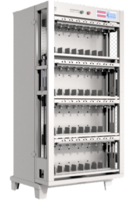
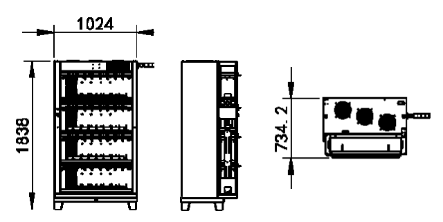
Below is the 3D appearance diagram of the equipment. Please note that the dimensions provided are for reference only and the actual dimensions may vary.
Dimensions: Length × Width × Height = 1024 mm × 734 mm × 1840 mm
1.1.4 Equipment Workflow Diagram
The equipment operates as follows:
1. Computer Control: The equipment is connected to a computer, which sends commands and collects data. The computer also monitors and controls the entire process.
2. Manual Operation: The device can also be manually operated using a keypad that displays various parameters and statuses.
3. Constant Current Board: The constant current board, controlled by the CPU, is responsible for maintaining constant current and voltage levels during operation.
4. Charging Process: When charging the battery, the bidirectional power supply converts AC (alternating current) into 14V DC (direct current). The constant current board then controls and monitors the charging process.
5. Discharging Process: During discharging, the process is reversed. The constant current board first raises the battery voltage to 15V, and the bidirectional power supply then converts this DC back into AC, which is fed directly into the factory's AC distribution network, thereby allowing the energy from the battery discharge to be recovered and reused.
1.2 Main Equipment Structure
1. Lithium battery formation and grading equipment.
2. Computer with USB interface (self-provided).
3. USB to 485 interface converter and communication cable.
4. Battery scanning system.
5. Product software.
2. Compatible Product Specifications and Fixture Types
2.1 Compatible Product Specifications
· Terminal Distance: 50-170mm
· Length: 90-220mm
· Thickness: 15-86mm
· Height: 80-220mm
2.2 Fixture and Tray Types
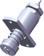
Custom fixtures.
3. Technical Specifications of the Equipment
|
Category |
Specification |
|
Equipment Structure |
|
|
Number of Channels |
Total 32 channels |
|
Chassis Color |
Standard gray/black (customizable) |
|
Fixture Type |
Flat-head clamp (optional alligator clip) |
|
Clamp Spacing |
81mm |
|
Channel Control Mode |
|
|
Control Mode |
Each battery has an independent constant current and constant voltage source, ensuring stability with no impact. Start, stop, pause, resume, and protection can be controlled. |
|
Each channel has independent constant voltage and constant current hardware control circuits. |
|
|
Charging and discharging current accuracy can be automatically calibrated via software for each channel. |
|
|
Real-time detection of contact resistance is available (four-wire system). |
|
|
Power Supply |
|
|
Operating Power |
Three-phase five-wire AC380V±10%, 50Hz |
|
Power Factor |
0.99 @220VAC, full load, grid THDu ≤2% |
|
Current Harmonics |
<5% @220VAC, full load, grid THDu ≤2% |
|
Power Efficiency |
Charging ≥80%, Discharging ≥70% |
|
Operating Power Consumption |
≤12KW |
|
Equipment Failure Rate |
<1% |
|
Temperature Monitoring |
Equipped with temperature sensors |
|
Status Indicators |
Three-color status light |
|
Cooling Method |
Natural air intake, upward exhaust |
|
Power Component Protection |
Protection for over-voltage, over-frequency, short-circuit, capacity, and other parameters. |
|
Channel Parameters |
|
|
Voltage Measurement Range |
DC 0~5V |
|
Battery Voltage Range |
Charging DC 0~4.5V; Discharging DC 4.5~2V |
|
Constant Voltage Range |
DC 2~4.5V |
|
Voltage Accuracy |
± (0.05% reading + 0.05% full scale) |
|
Voltage Control Resolution |
1mV |
|
Voltage Sampling Resolution |
1mV |
|
Current Range |
Charging DC 120mA ~60A; Discharging DC 120mA ~60A |
|
Current Accuracy |
± (0.05% reading + 0.05% full scale) |
|
Current Control Resolution |
1mA |
|
Current Sampling Resolution |
1mA |
|
Current Rise Time (90% load) |
≤50MS |
|
Channel Start Time (90% load) |
≤50MS |
|
Software Functions |
|
|
Control Method |
PC-controlled operation, full cabinet control, with scanning system |
|
Communication Method |
485 Serial communication (Baud rate 57600) / TCP communication |
|
Process Setting |
Up to 32 steps and 256 cycles |
|
Charging Mode |
Constant current, constant voltage, constant current & voltage |
|
Charging Cut-off Conditions |
Voltage, current, time, capacity, -△V |
|
Discharging Mode |
Constant current, constant power, constant resistance |
|
Discharge Cut-off Conditions |
Voltage, time, capacity |
|
Protection Functions |
Charging over-voltage, under-voltage, discharging over-voltage, under-voltage, trend protection, fluctuation protection, reverse polarity protection, etc. |
|
Time Range |
0 ~3000 minutes per step, time unit is in minutes |
|
Time Accuracy |
≤±0.1% |
|
Sampling Inspection Cycle |
1S-60S selectable |
|
Battery Sorting |
Sorting by capacity, time, open-circuit voltage, discharge platform, etc. |
|
Data Processing |
Logs voltage, current, time, capacity, and more. Automatically calculates constant current charge rate, capacity loss, discharge efficiency, average voltage, and midpoint voltage. |
|
|
Generates data curves and cycle diagrams. Outputs in text, Excel, Word, or MDB database formats. |
|
Software Features |
Various resumption features, barcode scanning support, data storage, batch data export, capacity sorting, pass/NG result judgment, comprehensive protection functions, etc. |
|
Calibration Cycle |
180-360 days |
|
Calibration Method |
Automatic software calibration |
|
Calibration Tools |
Optional high-precision calibration tools available |
|
Local Monitoring Computer |
|
|
Configuration Requirements |
OS: Windows 7 or above, Chinese (Simplified)/English Language; CPU: Intel i5 9th Gen or above; Memory: 8GB+; Hard Drive: 500GB+; Monitor: 21-inch or larger LCD; Dual network cards. |
4. Main Components of the Equipment
Standard Parts
|
No. |
Item |
Brand/Model |
Origin |
|
1 |
Microcontroller |
STM32 |
Imported/Domestic |
|
2 |
AD Chip |
High Precision AD |
Imported |
|
3 |
DA Chip |
High Precision PWM Modulation |
Imported |
|
4 |
Power Transistor |
ON Semiconductor/Blue Arrow |
Imported/Domestic |
|
5 |
Bidirectional AC/DC Inverter |
Custom |
Domestic |
|
6 |
Fixture |
TMAX |
Domestic |
5. Technical Requirements of the Equipment
5.1 Basic Operating Requirements
|
Specification |
Parameters |
|
Operating Environment |
-10℃ to 40℃ |
|
Relative Humidity |
≤80% |
|
Grounding |
Must be installed with a reliable safety ground line |
|
Cleanliness Control |
Cleanliness: ≤100,000 level; no corrosive gases, liquids, or explosive gases on site |
|
Noise Control |
Measured at 1000mm from the equipment: ≤75 dB |
5.2 Installation Requirements
|
Specification |
Parameters |
|
Operating Environment |
-10℃ to 40℃ |
|
Power Supply |
380V/50HZ/Three-phase |
|
Ground Requirements & Load |
Concrete floor, ≥650KG, no specific floor flatness requirement |
|
Network Requirements |
Reserved MES interface |
|
Access Dimensions |
Passage width > 3M, height > 3.5M; Door width 2.5M, height 3.5M |


 David@battery-equipments.com

