 English▼


- Battery Manufacturing Equipment
- Battery Laboratory Assembly Equipment
- Battery Pack Assembly Equipment
- Sodium Ion Battery Manufacturing Equipment
- Solid State Cell Production Line
- Dry Electrode Assembly Equipment
- Supercapacitor Assembly Equipment
- Perovskite Solar Cell Lab Equipment
- Li ion Battery Materials
- Ni / Al / Cu Metal Foam
- Customized Electrode
- Cathode Active Materials
- Anode Active Materials
- Coin Cell Parts
- Lithium Chip
- Cylindrical Cell Parts
- Battery Current Collectors
- Battery Conductive Materials
- Electrolyte
- Battery Binder
- Separator and Tape
- Aluminum Laminate Film
- Nickel Strip/Foil
- Battery Tabs
- Graphene Materials
- Cu / Al / Ni / Stainless steel Foil
- Battery Laboratory Equipment
- Li ion Battery Tester
- Battery Safety Tester
- Material Characterization Tester
- Rolling Press Machine
- Electrode Mixer
- Coin Cell Crimping Machine
- Coin Cell Electrode Disc Punching
- Pouch Cell Sealing Machine
- Pouch Cell Stacking Machine
- Pouch Cell Forming Machine
- Pouch Cell Ultrasonic Welder
- Pouch Cell Electrode Die Cutter
- Cylinder Cell Sealing Machine
- Cylinder Cell Grooving Machine
- Electrode Slitting Machine
- Cylinder Cell Winding Machine
- Cylinder Cell Spot Welding Machine
- Electrolyte Filling
- Type Test Cell
- Other Battery Making Machine
- NMP Solvent Treatment System
- Vacuum Glove Box
- Coating Machine
- Lab Furnaces
- Ball Mill
- Laboratory Press
- Laboratory Equipment
- Press Equipment
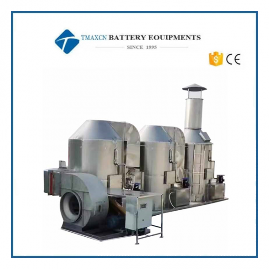
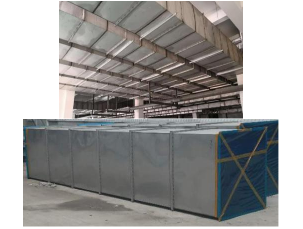
65000m3/H NMP Solvent Recovery System For Battery Electrode NMP Recycling
Model Number:
TMAX-PJ-NMP-65000Compliance:
CE compliantWarranty:
Two Year Limited Warranty With Lifetime SupportPayment:
T/T, Credit Card, Paypal, LC, Western UnionDelivery Time:
3 Days
65000m3/H NMP Solvent Recovery System For Battery Electrode NMP Recycling
I. Equipment and Engineering Introduction
1.1 Overview
This technical solution is applicable to the NMP recycling equipment system in new projects.
1.1.1 Basic function
The NMP recovery unit of this system utilizes the high boiling point (203 ℃) and mutual solubility of NMP with water. After heat exchange through the waste heat recovery device, the exhaust gas from the coating machine freezes and returns 90% to 95% of the total exhaust volume containing NMP. A small amount of 5% to 10% of the exhaust gas is adsorbed by the rotor, reaching a discharge rate of up to 40mg/m3. This recycling unit has high recycling rate, low operating cost, beautiful appearance, small footprint, superior performance, and easy operation. It can be widely used in the coating process of lithium battery production lines.
According to the first party's workshop, there is one double layer coating machine with an exhaust volume of 65000m3/h. The second party shall design two waste heat recovery units with a processing air volume of 32500m3/h and two NMP refrigeration treatment and recovery units with a processing air volume of 32500m3/h for the first party, and one 6500m3/h processing air volume rotary unit for secondary treatment.
This system mainly consists of a heat exchanger, a condensing and freezing unit, a middle and low efficiency filter, a positive exhaust wheel adsorption device, a waste liquid buffer tank, a conveying system, and a control system. The equipment operates automatically, achieving automatic recovery of the recovered liquid, maintaining stable temperature and humidity of the return air and VOCs content of the discharge air. The equipment adopts an overall system design, which can detect key process parameters and equipment operation status in real-time, ensuring the stability and safety of system operation.
1.1.2 Introduction to the modules of NMP recycling equipment functions
|
No. |
Item |
Technical requirement |
Notes |
|
1 |
System startup |
Configure a one click start recycling system; If it is necessary to start the coating machine in conjunction with the coating machine manufacturer, it is necessary to negotiate with both parties to reserve the interface. |
The remote touch screen can be installed next to the coating machine through negotiation with the buyer. |
|
2 |
system halt |
Delayed shutdown and sequential shutdown of the recycling system. |
It is beneficial for absorbing residual exhaust gas NMP and for system safety. |
|
3 |
Automatic control |
The PLC automatically controls the frequency converter to adjust the exhaust air volume of the fan based on the set value. |
Energy saving, wide adjustment range. |
|
PLC automatically controls the chilled water flow rate based on data such as intake temperature and exhaust temperature. |
Energy saving, meeting emission requirements. |
||
|
4 |
Monitoring and trend charts |
Set up on-site and remote touch screens with open network interfaces. |
Convenient monitoring. |
|
Online monitoring of intake temperature, exhaust temperature, and equipment operation status, including main fan frequency, cooling and chilled water temperature, and display of the above detected values. |
The parameters required for safety, energy consumption, and process can be monitored online. |
||
|
Trend chart of intake temperature and fan current. |
|
||
|
5 |
Give an alarm |
Sound, light, and color alarms. |
Easy to handle in a timely manner. |
|
6 |
Secure |
There are two touchscreen screens on site and the coating machine head for easy operation. |
|
|
The system considers measures to prevent liquid accumulation. The horizontal exhaust pipeline is designed with a slope, and the air duct from the coating machine side to the recycling system direction is from high to low, fully ensuring that there is no liquid accumulation in the air duct. The system considers measures to prevent liquid accumulation. The ventilation duct has a liquid groove to guide out the accumulated liquid and prevent it from accumulating in the ventilation duct. |
|
||
|
Set emergency stop button. |
Easy to handle emergency situations |
||
|
The system does not backflow. |
No fire hazards. |
||
|
Choose high-quality brand equipment that can meet the outdoor usage conditions of customers. |
|
||
|
7 |
Reliable |
System accessories can be easily cleaned, maintained, and replaced. |
|
|
8 |
Easy to use |
Automatically start and stop the coating linkage. |
|
1.1.3 Main Configuration List
|
Device Name |
Main configuration |
|||
|
Name |
Quantity |
Unit |
Brand |
|
|
Positive NMP recycling equipment |
Waste heat recovery device (gas heat exchanger) |
2 |
set |
TMAX |
|
Condenser |
2 |
set |
TMAX |
|
|
Filtering device |
2 |
set |
TMAX |
|
|
Tail gas turbine unit |
1 |
set |
TMAX(Wheel core body Ni Jiasi) |
|
|
10m3 waste liquid temporary storage tank |
1 |
unit |
TMAX |
|
|
Exhaust fan |
2 |
unit |
Guanggu/Xinfeng/Guangfeng |
|
|
Return fan |
2 |
unit |
Guanggu/Xinfeng/Guangfeng |
|
|
Inverter |
4 |
unit |
Yimeng Yite |
|
|
System electrical control cabinet |
2 |
set |
TMAX |
|
|
System components |
1 |
set |
Schneider |
|
|
NMP gas concentration meter |
3 |
set |
Herbalife/Yuante |
|
|
Temperature and pressure sensors |
2 |
set |
Shanghai Sipai/Huahan Instrument |
|
|
Stainless steel air duct system |
1 |
set |
National standard |
|
|
Liquid pipeline system |
1 |
set |
National standard |
|
|
System insulation materials |
1 |
set |
Rock wool/glass wool |
|
1.2 Equipment process flow
1.2.1 Flow Chart of Positive NMP Recovery Equipment Unit 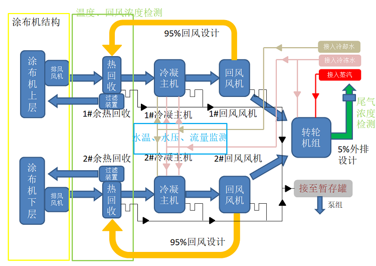
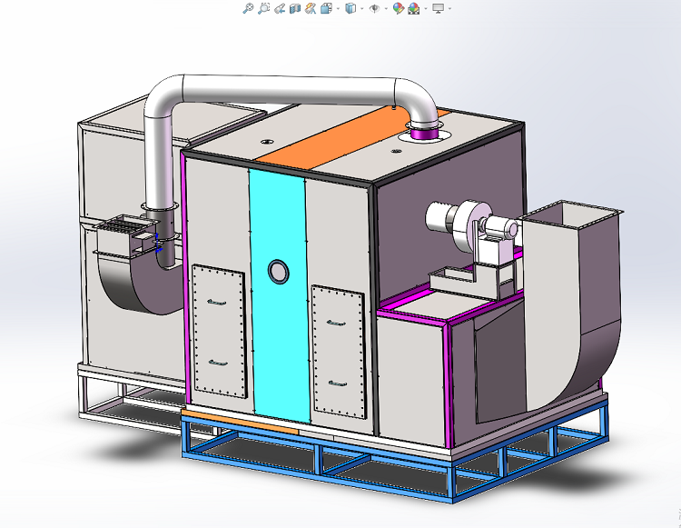
Process Description:
After passing through the heat exchanger, the positive electrode coating exhaust air undergoes two-stage condensation with room temperature cooling water and low-temperature chilled water. After reducing the NMP concentration, the total exhaust air volume of over 90% -95% is recycled and reused into the coating machine. Among them, about 5% -10% of the exhaust air volume is treated by the rotary absorption process to reduce the NMP concentration to below the allowable concentration for environmental emissions before being discharged at high altitude. All NMP condensate flows into the waste liquid temporary storage tank by gravity, and is transported and discharged by the discharge pump for external transportation.
Each double-layer positive electrode coating equipment is equipped with 2 sets of heat recovery and condensation recovery devices. The exhaust air is treated by the primary filter and the return air is treated by the medium efficiency before entering the coating machine; Two recycling equipment (equipped with a set of coating machine equipment) are equipped with a rotary adsorption device (i.e. one driven two). The rotary adsorption device uses municipal steam heating for regeneration, and the high-temperature regeneration air is discharged into the front end of the two-stage condensing device for further processing and recovery of NMP. After the wheel is processed, the air is collected into the main pipe and led out to the outdoor climbing wall for high-altitude discharge on the ceiling.
1.2.3 System 3D schematic diagram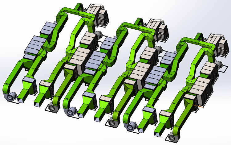
II. Technical requirements and execution standards for equipment design process
2.1 Equipment design process technical requirements
2.1.1 Design indicators of positive electrode NMP recovery system
|
No. |
Subject |
Given data |
Notes |
|
1 |
Single double-layer coating exhaust air volume |
65000m³/H |
Displacement at 130 ℃ exhaust temperature; |
|
2 |
Coating exhaust temperature |
130℃ |
The system should be able to withstand a high exhaust temperature of 160 ℃; |
|
3 |
Heat recovery efficiency |
80% |
|
|
4 |
Return air NMP concentration |
≤300ppm |
|
|
5 |
External exhaust ratio |
5%-10% |
|
|
6 |
Concentration of recycled waste liquid |
80% |
|
|
7 |
Tail gas emission concentration limit |
<25mg/m³ |
|
|
8 |
NMP recovery rate |
≥99.5% |
Continuous power on for more than 8 hours |
Heat recovery efficiency=(for the return air temperature of the coating machine - temperature after condensation recovery) ÷ (for the exhaust air temperature of the coating machine - inlet temperature on the cold side)
2.2 Energy consumption of positive electrode NMP recovery system
(1)Power demands
|
Device Name |
Single unit power |
Number of single set machines |
Total power per unit |
Total power of a single set of machines |
|
|
kW |
set |
kW |
kW |
||
|
Positive NMP recovery system |
Exhaust fan |
55 |
2 |
115 |
230 |
|
return fan |
55 |
2 |
|||
|
Processing fan |
5.5 |
1 |
|||
|
Regeneration fan |
2.2 |
1 |
|||
|
Wheel motor |
0.55 |
1 |
|||
|
NMP waste liquid tank area |
Magnetic pump |
4 |
2 |
4.4 |
4.4 |
(2)Water demand
|
Project |
Dosage(m³/h) |
Number of condensers (set) |
Total demand(m³/h) |
Single condenser interface |
Water quality requirements |
Notes |
|
Cooling water |
25 |
2 |
50 |
65 One input and one return two interfaces |
Pressure ≥ 0.3Mpa |
Calculated based on a temperature difference of 5 ℃ |
|
chilled water |
33 |
2 |
66 |
80 one in, one back, two interfaces |
7 ℃ in/12 ℃ out |
Calculated based on a temperature difference of 5 ℃ |
(3)Dry compressed air demand
|
Project |
Single unit usage (L/min) |
Number of valve groups (set) |
Total demand (L/min) |
Interface specifications |
Water quality requirements |
Notes |
|
Runner pneumatic valve group |
150 |
1 |
300 |
φ 8PE pipe |
Pressure ≥ 0.6Mpa, 0 ℃ dew point |
|
(4)Steam demand
|
Project |
Single unit usage(kg/h) |
Number of valve groups (set) |
Total demand (kg/h) |
Interface specifications |
Water quality requirements |
Notes |
|
steam |
98 |
1 |
98 |
DN32 |
Pressure ≥ 0.6Mpa, ≥ 159 ℃ |
|
2.3 Design shall comply with international and Chinese national standards
|
No. |
Standard |
Name |
|
1 |
GB30484-2013 |
Emission standards for pollutants in the battery industry |
|
2 |
GB3095-2012 |
Environmental Air Quality Standards |
|
3 |
GB/T50087-2013 |
Design code for noise control in industrial enterprises |
|
4 |
GB50054-2011 |
Design Specification for Low Voltage Power Distribution |
|
5 |
GB50052-2009 |
Code for design of power supply and distribution systems |
|
6 |
GB50055-2011 |
Code for design of power distribution for general electrical equipment |
|
7 |
GB50016-2014 |
Code for Fire Protection Design of Buildings |
|
8 |
AQ3009-2007 |
Safety Code for Electrical Explosion Protection in Hazardous Areas |
|
9 |
GB50057-2010 |
Design code for lightning protection of buildings |
|
10 |
GB50011-2010 |
Code for Seismic Design of Buildings |
|
11 |
GB50316-2000 |
Code for design of industrial metal pipelines |
|
12 |
GB3836.1-2000 |
General requirements for electrical equipment used in explosive gas atmospheres |
|
13 |
GB50235-2010 |
Code for construction of industrial metal pipeline engineering |
|
14 |
GB/T14976 |
Stainless steel seamless steel pipes for fluid transportation |
|
15 |
GB 50058 |
Code for design of electrical installations in explosive hazardous environments |
|
16 |
GB 50116-2013 |
Code for design of automatic fire alarm |
|
17 |
GB 50015-2003 |
Code for design of building water supply and drainage |
III. Equipment functions and main technical parameters
3.1 Basic equipment specifications and parameters
3.1.1 Positive pole NMP recovery system equipment
(1)Condenser host
|
No. |
Parameter |
Parameter value |
Notes |
|
1 |
Model |
PJLN-125K |
|
|
2 |
Equipment appearance |
SUS304 natural color, carbon steel base (with anti-corrosion treatment), the external surface of the equipment should be free of obvious scratches, rust spots, and indentations, the surface should be smooth and clean, the spraying layer should be uniform, the color tone should be consistent, without cracks, bubbles, and peeling, weather change resistance, corrosion and rust resistance, strong strength, good insulation performance, good sound and vibration insulation performance, non-toxic, and odorless |
|
|
3 |
Equipment size |
2500x2200x3200mm |
Based on the factory size |
|
4 |
Equipment weight |
6 tons (subject to factory parameters) |
Operating weight |
|
5 |
Equipment noise |
meet a requirement |
|
(2)Waste heat recovery device (gas exchanger)
|
No. |
Parameter |
Parameter value |
Notes |
|
1 |
Model |
PJYR-BS-65K |
|
|
2 |
Equipment appearance |
The high-efficiency plate type aluminum heat exchange core is covered with stainless steel outside, and the external surface of the equipment should be free of obvious scratches, rust spots, and indentations. The surface should be smooth and clean, with a uniform spraying layer and consistent color tone, without cracks, bubbles, and peeling. It is resistant to climate change, has strong corrosion and rust resistance, good strength, good insulation performance, good sound and vibration insulation performance, non-toxic, and odorless |
|
|
3 |
Equipment size |
About 1500x1500x3330mm |
Based on the factory size |
|
4 |
Equipment weight |
4 tons (subject to factory parameters) |
Operating weight |
(3)Centrifugal fan
|
No. |
Parameter Name |
Parameter value |
Notes |
|
1 |
Model |
Y6 series |
|
|
2 |
Equipment appearance |
The breathable part SUS304 is equipped with a rubber shock absorber pad and a carbon steel base (with anti-corrosion treatment). The external surface of the equipment should be free of obvious scratches, rust spots, and indentations, and the surface should be smooth and clean. The spraying layer should be uniform, with consistent color tone, without cracks, bubbles, and peeling. It is resistant to climate change, corrosion and rust, has strong strength, good insulation performance, good sound and vibration insulation performance, non-toxic, and odorless |
|
|
3 |
Equipment size |
2870*1870*2600mm |
Based on the factory size |
|
4 |
Equipment weight |
3 tons |
/ |
|
5 |
Equipment noise |
meet a requirement |
|
(4)Runner unit
|
No. |
Parameter Name |
Parameter value |
Notes |
|
1 |
Model |
PJZL-6.5K |
|
|
2 |
Equipment appearance |
The external surface of the equipment should be free of obvious scratches, rust spots, and indentations, with a smooth and clean surface, uniform spraying layer, consistent color tone, no cracks, bubbles, and peeling. It is resistant to climate change, has strong corrosion and rust resistance, good strength, good insulation performance, good sound and vibration insulation performance, non-toxic, and odorless |
|
|
3 |
Equipment size |
4000*2580*3250mm |
Based on the factory size |
|
4 |
Equipment weight |
4 tons (subject to factory parameters) |
Operating weight |
|
5 |
Equipment noise |
Meets requirements |
|
(5)10 ton NMP waste liquid temporary storage tank
|
No. |
Parameter Name |
Parameter value |
Notes |
|
1 |
Equipment appearance |
The external surface of the equipment should be free of obvious scratches, rust spots, and indentations, and the surface should be smooth and clean, without cracks, bubbles, and peeling. It should have strong resistance to climate change, corrosion and rust, good strength, non-toxic, and odorless properties |
|
|
2 |
Equipment size |
Φ2200*2700mm |
Based on the factory size |
|
3 |
Equipment weight |
1.0 tons (subject to factory parameters) |
|
3.1.3Air duct engineering
|
No. |
Parameter Name |
Parameter value |
Notes |
|
1 |
process characteristics |
Full welding, acid cleaning and passivation of the weld surface |
The pressure test of the air duct is 1.5 times the design pressure, and there is no deformation or pressure drop for 1 hour |
|
2 |
exterior |
The external surface of the equipment should be free of obvious scratches, rust spots, and indentations, and the surface should be smooth and clean, without cracks, bubbles, and peeling. It has strong corrosion and rust resistance, is non-toxic, and has no odor |
|
|
3 |
material quality |
All made of high-quality stainless steel |
SUS304 stainless steel air duct thickness ≥ 1.5 ± 0.15mm |
|
4 |
heat preservation |
Wrap the air duct with insulation cotton of 50mm or more, and then wrap it with aluminum foil cloth. |
|
|
5 |
clean |
Wipe with a white cloth without dust |
Clean and wipe in the production workshop before sealing with cling film until installation on site |
3.2 Description of each module of the equipment
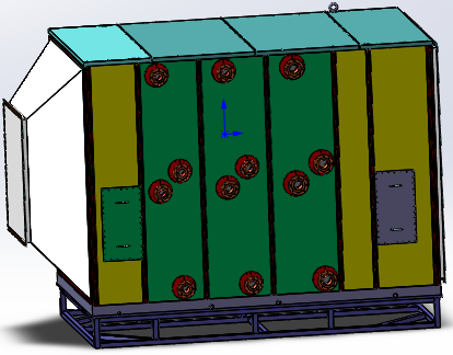
3.2.1Positive electrode waste heat recovery device
The working temperature of the coating machine is about 150 ℃. The circulating fan in the oven section extracts hot air from the oven and circulates it with some fresh air (which is heated to the process temperature through electricity, steam, oil, etc.) to achieve the purpose of drying the electrode. The heat recovery equipment uses the high-temperature exhaust gas generated by the coating machine as the heat source and heats the return air into the coating machine through a heat exchanger.
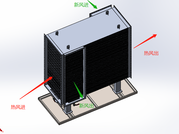
|
Reference stereogram of positive electrode waste heat recovery
|
|
Functional module technical configuration: |
|
No. |
Item |
Technical Parameter |
|
1. |
Gas gas heat exchange |
The processing air volume is 32500m3/h, using a vacuum brazing aluminum plate cross flow structure, and the box is made of stainless steel |
|
2. |
support |
The air passage part is made of stainless steel and aluminum, and the bracket is made of carbon steel. A 50mm thick double layer insulation design is made, and the flange connection at the interface is used to support waste heat recovery. |
|
3. |
Temperature transmitter |
Integrated temperature transmitter PT100, temperature measurement range 0-200 ℃, accuracy ± 1 ℃, quantity: 4; Cold and hot air inlet and outlet, one each |
|
4. |
Return air NMP concentration meter |
The range is 0-1000ppmppm, with an accuracy of 5%, installed in the hot air inlet and cold air outlet positions of the NMP recovery device. |
|
5. |
Filtering device |
Install a medium efficiency filter at the return air outlet of the heat recovery module to filter the return air of the coating machine |
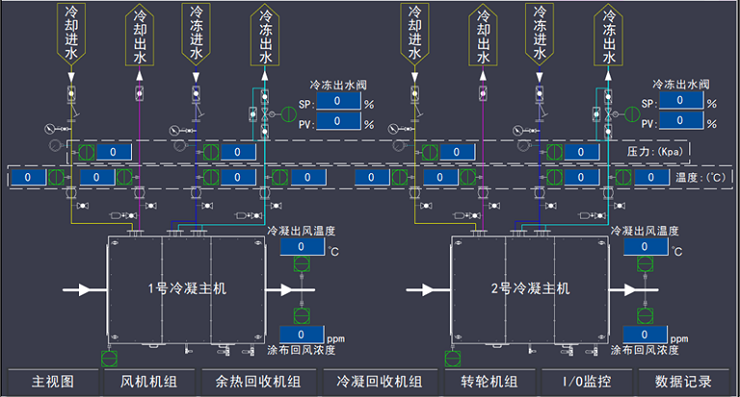
3.3.2 Positive condensation host module
Function: Conduct NMP recovery treatment on waste gas containing NMP, and transport the recovered air to the coating machine. Further precipitation of NMP is achieved through the cold plate of a chilled water meter.
Install a gas-liquid separator (defoamer) at the outlet of the NMP recovery host to effectively prevent condensation of NMP droplets into mist, prevent NMP accumulation when sent to the return air pipeline, and prevent foggy NMP droplets from being re gasified after being heated by waste heat recovery, thus avoiding an increase in the concentration of NMP in the return air entering the coating machine.
Functional module technical configuration
|
|
||
|
No. |
Project |
Technical parameter |
|
1. |
Condensation host |
Processing air volume 32500m3/h, material SUS304 |
|
2. |
Surface cooler |
The tube fin type adopts a countercurrent combination to achieve gas-liquid heat exchange. |
|
3. |
Wire mesh mist eliminator |
Made of stainless steel, it removes small particles and droplets suspended in the exhaust gas. |
|
4. |
Liquid receiving chassis |
Anti seepage and corrosion-resistant liquid collection tray |
|
5. |
G4 primary filter |
Installed inside the box near the air inlet and equipped with an access hole |
|
6. |
Support |
10 # channel steel base, made of carbon steel |
|
7. |
Temperature transmitter |
Integrated temperature transmitter PT100, temperature measurement range 0-50 ℃, accuracy ± 1 ℃. Installation location: one for each inlet and outlet of chilled water. |
|
8. |
Pressure transmitter |
0-0.5Mpa, explosion-proof, with an accuracy of 2.5%, 1 quantity, installation position: 1 frozen inlet |
|
9. |
Electric two-way regulating valve |
The valve body material is ductile iron, and the sealing material is EPDM rubber; Valve plate stainless steel 304; Quantity: 1, installation position: chilled water outlet |
3.3.3 Exhaust gas treatment wheel adsorption module
|
|
|
Functional module technical configuration |
|
No. |
Project |
technical parameter |
|
1. |
Runner specifications |
Φ 550 * 400mm, high-efficiency zeolite molecular sieve structure, maximum processing air volume 17500m3/h |
|
2. |
Fever package |
Municipal steam heating |
|
3. |
Tail gas NMP concentration meter |
The range is 0-100ppm, with an accuracy of 5%, and is installed at the position of the outer exhaust port. |
Technical description:
The processing air volume of the NMP rotary processing device (adsorption and desorption processing air cabinet) shall not be less than 10% of the total exhaust air volume of the system. The design and selection of the equipment and combined accessories should meet the following requirements:
① The runner must be made of non flammable material and have the ability to regenerate below 202 ℃ (boiling point temperature of NMP);
② The regeneration of the runner adopts steam coil heating method for regeneration. To ensure the structural strength of steam regeneration type heat coils, stainless steel material should be used and its working pressure capacity should be greater than the steam supply pressure and not less than 0.6Mpa.
③ The rear end of the wheel adsorption treatment is equipped with an NMP concentration sensor to ensure that the exhaust emission concentration meets the overall emission indicators of the system.
④ The regenerative air of the runner should be obtained from the post adsorption treatment section of the runner, and fresh air should not be sucked in from outside unless otherwise specified.
⑤ Temperature sensors should be installed at both the front and rear ends of the regeneration device, and the regenerated high-temperature gas should be recycled through heat exchange before entering the NMP condensation treatment section for further processing;
3.3.6 Overview of Control System Technology
1) Control system: PLC is used for system control, with a touch screen human-machine interface to achieve real-time operation of the unit operation and display of real-time data during unit operation. Mainly completing management, operation, data reporting, parameter settings, including monitoring of system operation status (online monitoring of tank liquid level, intake temperature, exhaust temperature, and all equipment operation status), data collection, fault (while displaying detailed fault information), and able to achieve LAN connection, network control, and data sharing. The system is equipped with a one button start stop function, which has two modes: manual and automatic, and linkage start stop function with the coating machine.
2) The automatic control system of the unit has a TCP/IP protocol interface.
3) The NMP recycling host and coating machine have linkage function:
After the coating machine is started, the operator needs to use the remote control system (touch screen display) to turn on the recycling device. When the recycling device is not turned on, the coating machine cannot perform coating operations;
After the coating machine is turned off, the operator of the coating machine needs to use a remote control system (touch screen display) to turn off the recycling device. If the coating machine does not stop working, the recycling device cannot stop working; After the coating machine is shut down, the NMP recovery device has a delayed shutdown function;
When the recycling device suddenly stops due to a malfunction, the coating machine should stop working or issue an alarm; The linkage control work is jointly completed by the coating machine manufacturer and the heat recovery device manufacturer;
4) If there is no special explanation for the supporting electronic control of the positive NMP recovery system and negative heat recovery system, the hardware design should not only achieve the above requirements, but also meet the following technical requirements:
The distribution control cabinet should be equipped with a total control circuit breaker switch with a rated short circuit breaking capacity greater than 50KA, and equipped with a multi-functional electricity meter to display the total operation of all equipment in the system, the operation of the main exhaust fan equipment, and the operating current, power, and cumulative power consumption of the wheel recycling and regeneration device.
When the condensation recovery device and the runner recovery device are relatively separate, but the electrical control of the equipment that supports the same set of coating machine should be combined and the graphic display should be integrated and displayed together;
All signal circuits input from the C cabinet to the outside or inside should be connected through jumper terminals and should not be directly connected. The terminal block adapter wire number, specification, and position should be completely consistent with the electrical schematic drawings accompanying the cabinet.
The automatic control system of the d unit has a TCP/IP protocol interface, which enables the upper computer to read all parameter information displayed on the human-machine interface and provide data signal address encoding information to the upper computer.
E boxes and cabinets are raised by hanging walls or setting foundation channel steel, with a distance of no less than 150mm from the ground to prevent the risk of water stains. When outdoor cabinets are installed, stainless steel boxes should be used and necessary measures should be taken to prevent sun, rain, ventilation, and heat dissipation.
The distribution box and cabinet should be equipped with exhaust and heat dissipation devices, and the hourly ventilation and exhaust air volume of the box should not be less than 20 times the volume of the box; The box is equipped with an automatic lighting device for opening the door;
5) The distribution cabinets and automatic control cabinets of the recycling system can be combined and set up when space conditions permit. The automatic control system is equipped with a touch control screen of no less than 10 inches as the human-machine interface. The graphical control interface can display the gas processing process of each functional section, and can implement jog and start stop control on key equipment in manual control mode. The entire automatic control system should be able to achieve the following automatic control functions:
The chilled water inlet volume, total system inlet and recovery air volume (fan automatic variable frequency adjustable), and exhaust gas exhaust air processing air volume (fan variable frequency adjustable) are instantly and continuously adjustable;
B Control the operation (manual/automatic) of the main supply and exhaust fan, the rotation wheel driving motor, and the operating frequency of the regeneration fan;
Display the NMP concentration information of the total return air of the system; Information on NMP concentration discharged from the system;
Display the opening of each control valve group; NMP liquid level parameters of temporary storage tank;
Display the total inlet and return air temperature of the system, the wind speed inside the main inlet air duct (calculated as the total air volume of the displayed system), the air temperature before and after cold disk processing, the inlet temperature of chilled water and cooling water, the outlet air temperature of the runner regeneration heating device, and the exhaust air temperature of the runner regeneration;
The total operating power and current of the f system, the power and current of the regenerative heating device, and the operating power and current of the main inlet and exhaust fans; Operation status information of coating machine equipment;
G has alarm information indications such as wheel stop, fan overload and overcurrent, regeneration temperature over temperature, temporary storage tank full liquid level, coating machine inlet and exhaust NMP concentration, and system discharge NMP concentration over warning.
6) The automatic control system of the unit has a TCP/IP interface, which enables the upper computer to read all parameter information displayed on the interface and provide data signal address encoding information to the upper computer. Save and record the operating status of the unit, data from various detection points, and alarm information for at least 30 days.
7) After the system is installed and debugged, in the state of production startup and operation, with the consent and approval of the owner, reasonable instruments and methods are used to measure and verify the system's exhaust processing capacity and operating temperature status. And invite a third party to sample and test the concentration and composition of the system's exhaust gas, and issue a testing report to ensure the reliability of the system's operation.
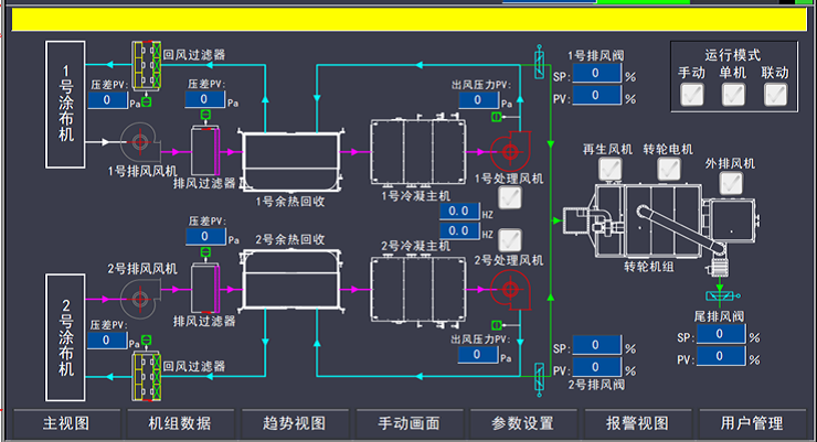
Human machine interaction control panel
3.3.7 Overview of Air Pipe Engineering Technology
1) When installing the circulating air duct, there is a 0.1% slope towards the waste heat recovery and recovery host to prevent the discharge of NMP liquid in the duct.
2) After the installation of the air duct is completed, a pressure test should be conducted. Before the air duct sealing test, both ends of the air duct should be sealed with glue. After sealing, the air should be blown and compressed to 2500pa. After stopping the air supply, the pressure should be maintained for 1 hour. If the air duct does not deform and there is no pressure drop, it is considered qualified. The air duct sealing test is a hold point, and the next step of air duct connection work can only be carried out after confirmation by the owner.
3) All exhaust and return air ducts of the coating machine equipment are fully welded using SUS304 stainless steel argon arc welding without special instructions, and the thickness of the air duct is 1.5 ± 0.1mm. If space conditions permit, circular air ducts are preferred, and the reinforcement of rectangular air ducts is designed using a combination of stainless steel angle steel reinforcement frame reinforcement and rectangular reinforcement. After stainless steel welding, all weld surfaces should be cleaned to remove oil stains, welding slag, and splashes. Acid pickling and passivation paste should be used for pickling and passivation, and clean with clean water.
4) The outdoor exhaust duct of the positive electrode coating machine after being adsorbed by the rotary wheel is not equipped with insulation, and is discharged at a height of more than 3 meters from the roof of the building where it is located. The discharge outlet should be equipped with reasonable rainproof and windproof measures, and the exhaust outlet should be equipped with a steel testing and sampling platform that meets local environmental acceptance requirements and an exhaust outlet testing and sampling port.
5) All air ducts and fan shells of the coating machine recycling system should be insulated with rock wool or fiber wool with a thickness of no less than 50mm.
6) The design of the air duct for the recycling system should be deepened based on the actual space on site, reasonably avoiding other functional pipelines and building structures, and reasonably setting up various functional sensors to achieve the functions mentioned in this requirement. The valve groups, sensors, and sampling ports on the air duct should be located in a reasonable and operable space. The design wind speed of all air ducts is 15m/s. Slope discharge pipes should be installed on air ducts and devices that may produce condensation and liquid accumulation, with a slope towards the recovery and treatment device or discharge outlet.
7) Purpose and main components:
Transport NMP exhaust gas, connect various components of the coating machine and NMP recycling equipment, and discharge environmentally friendly air. Pull rod, rock wool insulation cotton, reinforcing ribs, insulation part wrapped in aluminum sheet, fan interface installation soft connection, identification, etc
8) Direction process:
Positive electrode: coating machine → waste heat recovery → NMP recovery equipment → waste heat recovery → coating machine
Negative electrode: hot air discharged from the coating machine → heat exchange → fresh air filtration → heat exchange → return air from the coating machine
9) Structural diagram
10) Configuration Description
|
Institution Name |
Configuration Description |
Notes |
|
SUS304 stainless steel air duct |
The wind speed of the ventilation duct is about 15m/s, and the return air speed is ≤ 15m/s. SUS304 stainless steel plate is fully welded and cleaned. |
|
|
Tie rod |
Fixed air ducts and buildings |
|
|
Rock wool/fiber cotton insulation cotton |
Stainless steel air ducts are insulated externally to ensure internal temperature and reduce heat dissipation. |
|
|
Reinforcing rib |
Stainless steel material, reinforced on the outside of the air duct, reduces the vibration of the air duct during airflow. |
|
|
Soft connection |
High temperature and NMP corrosion resistance, installed in the connection with the fan to reduce vibration of the air duct caused by moving parts |
|


 David@battery-equipments.com

